SL1620 User Guide
Introduction
The Astra Machina Foundation Series of evaluation-ready kits enable easy and rapid prototyping for the Synaptics SL series of multi-modal embedded processors. A modular design incorporates swappable core compute modules, a common I/O board, and daughter cards for connectivity, debug, and flexible I/O options.
The Synaptics Astra SL-Series is a family of highly integrated AI-native Linux and Android SoCs optimized for multi-modal consumer, enterprise, and industrial IoT workloads with hardware accelerators for edge inferencing, security, graphics, vision, and audio. The SL1620 is designed and optimized for embedded applications that require powerful processing, advanced AI capability, and 3D graphics. This chip comes with Linux® OS, superior audio algorithms, a variety of peripherals, dual displays, companion Synaptics SoC for connectivity and audio front end.
Scope
This user guide describes the hardware configuration and functional details for the Astra Machina SL1620 core module, I/O card, and supported daughter cards, in addition to the bring-up sequence for the evaluation kit.
Definition of Board Components
Astra Machina: Combined system with core module, I/O board, and supported daughter cards.
Core module: Processor subsystem module with key components including SL1620, eMMC, and DDR4.
I/O board: Common base board that includes various standard hardware interfaces, buttons, headers, and power-in.
Daughter card: Add-on boards for supporting various features such as connectivity, debug, and other flexible I/O options.
Astra Machina System Overview
This section covers system features, block diagrams and top views of the Astra Machina evaluation kit.

SL1620 core module (Dimensions: WxH = 69.6 x 47.38mm)

I/O board
Features
The SL1620 evaluation system includes the following components:
Main components on the core-module:
- Synaptics SL1620 Quad-Core Arm Cortex-A55
Embedded IoT Processor, up to 1.9 GHz
Storage: eMMC5.1 (16 GByte)
DRAM: x32 2GB system memory by 2pcs x16, 8-Gbit, DDR4-2133
PMIC: support DVFS in Vcore supply rail
SD Card Receptacle
Line-out: direct Line Level 2.1-VRMS stereo output
DMIC: 2 digital microphones – 1 PDM stereo audio input
LCDC(RGB): on 54-pins FPC connector to support RGB 16bpp, 18bpp and 24bpp output formats; up to 1080p30 screen resolution
Main components on I/O board:
M.2 E-key 2230 Receptacle: It supports SDIO, UART for WiFi/BT modules
USB 3.0 Type-A: 4 ports to supports host mode at SuperSpeed
USB 2.0 Type-C: supports OTG host or peripheral mode at Hi-Speed
Push buttons: used for USB-BOOT selection and system RESET
2pin Header: used for SD-BOOT selection
Off-board daughter card interface options:
MIPI DSI on 22-pin FPC interface to support 4-lane DPHY plus I2C and GPIOs for up to 1080p60 display panel
ISP 12-pin daughter card to support offline program SPI NOR flash on Core-Module
JTAG daughter card for debug
40-pin header for additional functions
4-pin PoE+ daughter card to support an add-on voltage regulator module for PoE+ Type2 (802.3at) power device; available power shall be 25.5W (Class 4) at 5Vpins of 40-pin header to I/O board
4-pin connector for active Fan with PWM
Type-C power supply with 15V @ 1.8A
SL1620 system block diagram
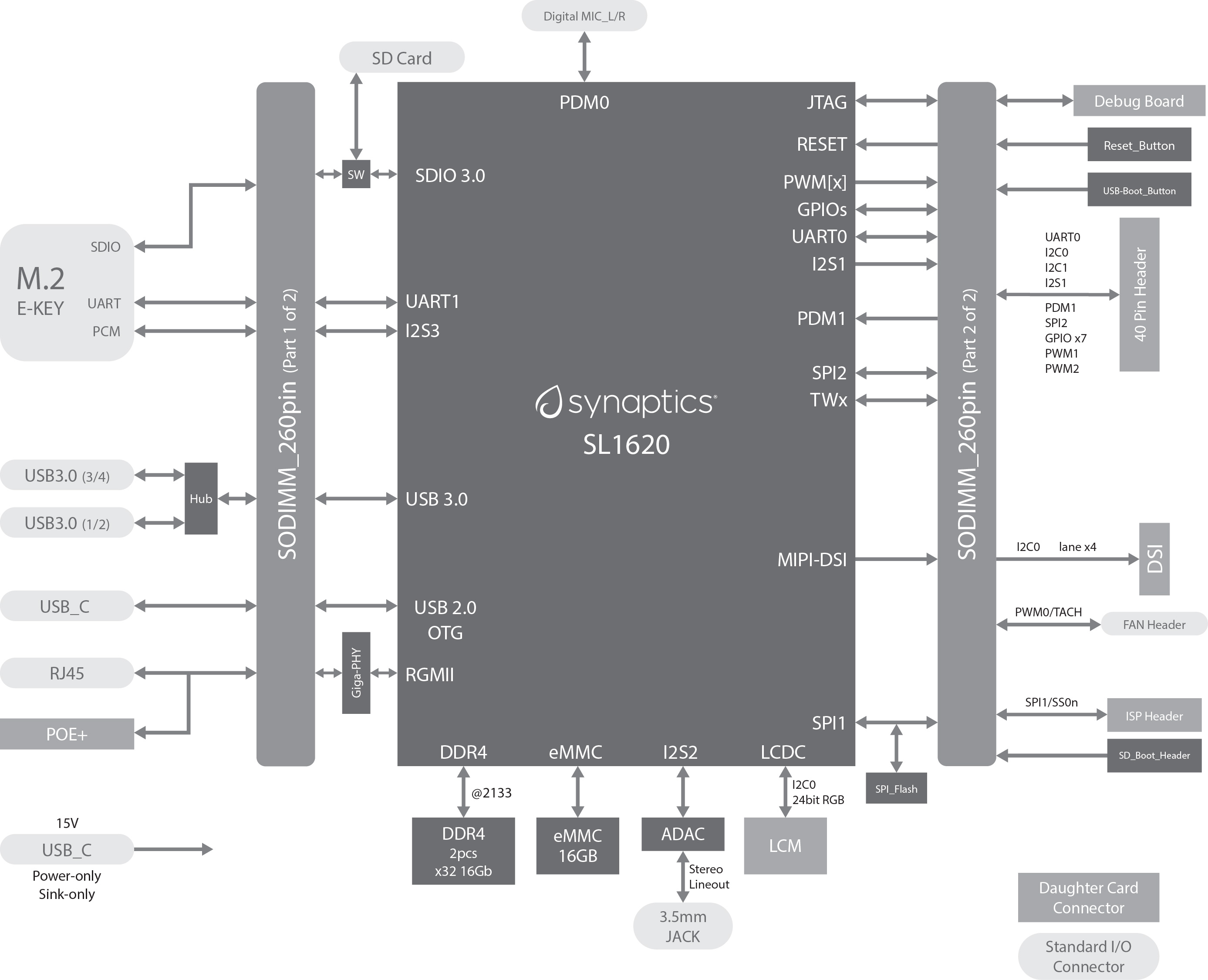
SL1620 system block diagram
Top view of SL1620 Astra Machina Evaluation System
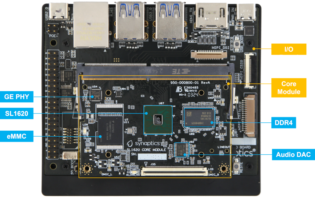
Top view of SL1620 evaluation system
System connectors
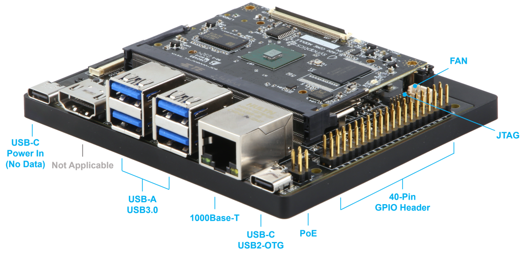
Front view
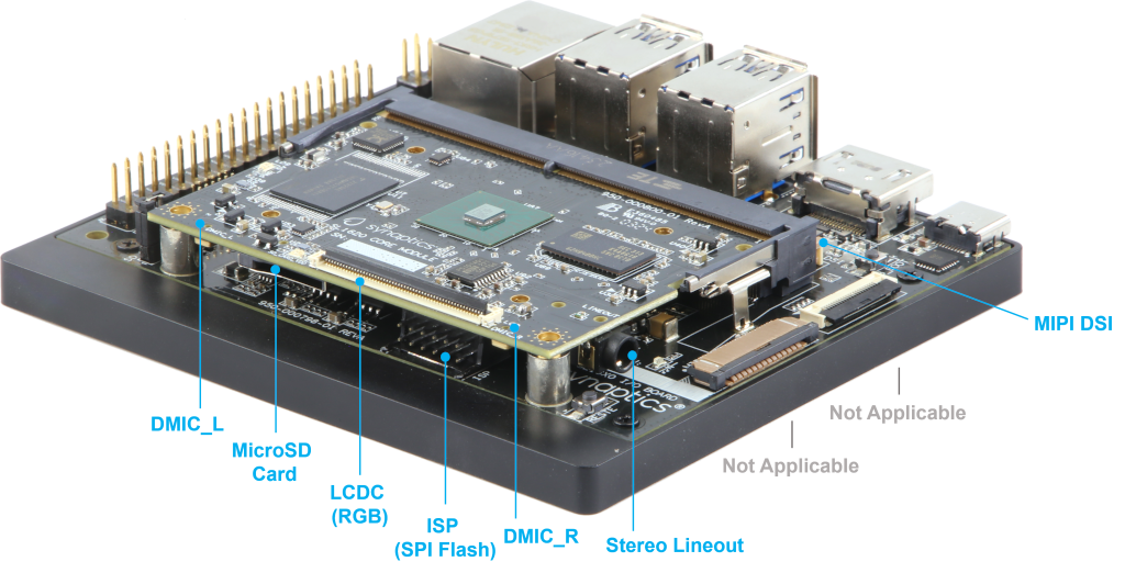
Rear view
Astra Machina Board Control/Status & System I/O
This section covers booting up, LEDs status indicators, buttons, connectors, and pin-strap settings.
Booting up
There are three types of booting up, select one bootup before powering on the Astra Machina.
eMMC boot: Default booting up.
SD boot: Short SD_Boot header by 2.54mm jumper-cap before power-up, see SD_Boot header in Locations of jumper on I/O board. Ensure SD-Card with firmware is plugged into SD-slot on Core Module in Locations on core module bottom side.
USB boot: Connect USB-C usb2.0 port to the host PC, then follow the procedure in section 2.4.
LEDs
LED locations
LED locations on I/O board shows the LED locations on the I/O board.
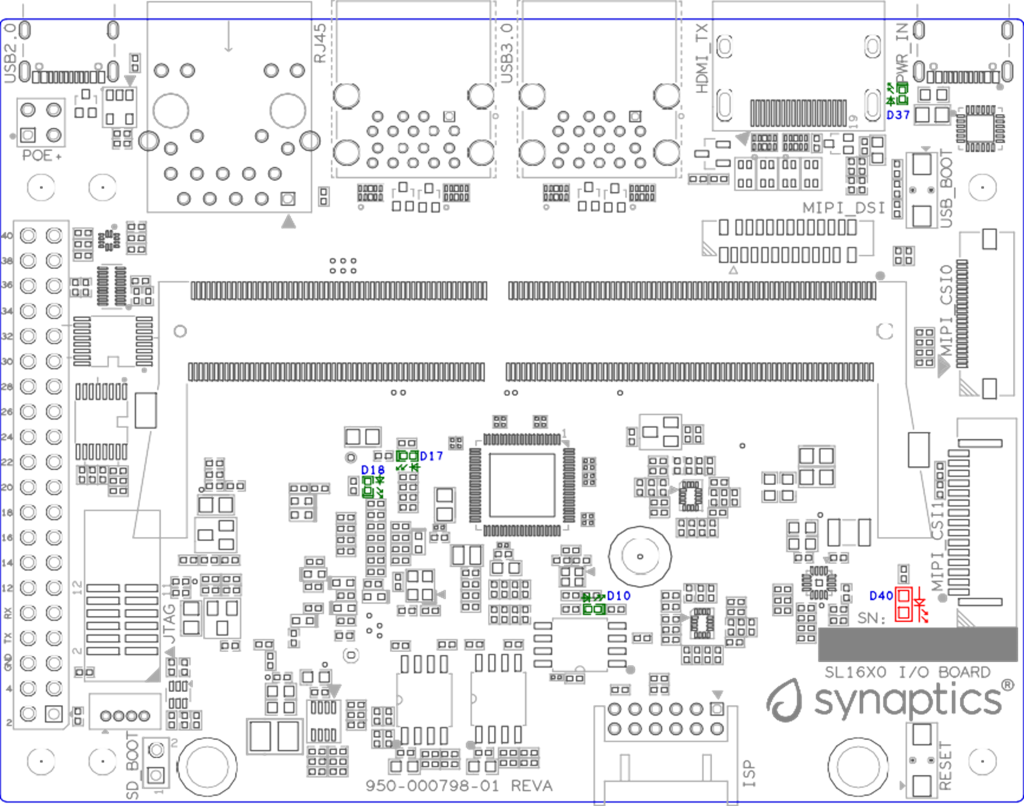
LED locations on I/O board
LED definitions
LED |
Color |
LEDs Function |
|---|---|---|
D10 |
Green |
LED indicator for USB3.0 Hub is working in normal mode or suspend mode. |
D17 |
Green |
LED indicator1 for M.2 device general purpose. |
D18 |
Green |
LED indicator2 for M.2 device general purpose. |
D37 |
Green |
LED indicator for USB-C PD power source status. |
D40 |
RED |
LED indicator for Stand-by status. |
SoC Pinstrap and Bootup Settings
Pad Name |
Strap Name |
Setting Value Default* |
Resistor Stuffing
|
Description Rpu = OnChip Pull-up Rpd = OnChip Pull-down |
|---|---|---|---|---|
TEST_EN |
TEST_EN |
— |
— |
SM TEST Enable (Rpd) |
0* |
-R120 |
0: Enable ARM ICE JTAG connections (CoreSight) |
||
1 |
+R120 |
1: Enable SCAN or BSCAN tests |
||
JTAG_SEL |
JTAG_SEL |
— |
— |
SM JTAG Port Selection (Rpd) |
0* |
-R121 |
0: ARM ICE JTAG connections |
||
1 |
+R121 |
1: Reserved for factory use |
||
POR_EN |
POR_EN |
— |
— |
Power-on reset (POR) bypass (Rpu) |
0 |
+R4 |
0: Bypass on-chip POR generator |
||
1* |
-R4 |
1: Enable on-chip POR generator |
||
PWM[0] |
cpuRstByps |
— |
— |
CPU reset bypass strap (Rpd) |
0* |
-R116 |
0: Enable reset logic inside CPU partition |
||
1 |
+R116 |
1: Bypass reset logic inside CPU partition |
||
SPI2_SCLK |
pllPwrDown |
— |
— |
SYS/MEM/CPU PLL Power Down; Note: pllPwrDown should be set to 1 only when pllByps is also set to 1. (Rpd) |
0* |
-R123 |
0: Power up |
||
1 |
+R123 |
1: Power down |
||
USB2_DRV_ |
pllByps |
— |
— |
SYS/MEM/CPU PLL bypass indicator |
VBUS |
||||
0* |
-R124 |
0: No bypass |
||
1 |
+R124 |
1: All PLL bypassed |
||
SPI2_SS0n |
software_strap[1] |
— |
— |
Straps for software usage (Rpd) |
0* |
-R117 |
— |
||
1 |
+R117 |
— |
||
SPI1_SDO[0] |
software_strap[2] |
— |
— |
Straps for software usage (Rpd) |
0* |
-R118 |
— |
||
1 |
+R118 |
— |
||
SPI1_SCLK[1] |
software_strap[3] |
— |
— |
Straps for software usage (Rpd) |
0* |
-R119 |
— |
||
1 |
+R119 |
— |
||
I2S1_DO |
boot_src[0] |
— |
— |
CPU Boot Source bit [0] (Rpu). See boot_src[1:0]. 2’b00: SPI-Secure Boot 2’b01: ROM boot from NAND 2’b10: ROM boot from eMMC 2’b11: SPI-Clear boot |
0* |
R105 |
ROM boot from SPI. |
||
1 |
R107 |
ROM boot from NAND. |
||
I2S2_DO |
boot_src[1] |
— |
— |
CPU Boot Source bit [1] (Rpd). See boot_src[1:0]. 2’b00: SPI-Secure Boot 2’b01: ROM boot from NAND 2’b10: ROM boot from eMMC 2’b11: SPI-Clear boot |
0 |
R108 |
ROM boot from SPI. |
||
1* |
R106 |
ROM boot from eMMC. |
||
I2S3_DO |
Legacy_boot |
— |
— |
Strap to reduce reset wait time (Rpd) |
0* |
-R122 |
0: 2 ms |
||
1 |
+R122 |
1: 20 ms |
Net Name |
Strap Name |
Setting Value Default* |
Resistor Stuffing
|
Description Rpu = OnChip Pull-up Rpd = OnChip Pull-down |
|---|---|---|---|---|
USB_BOOTn |
USB-Boot |
— |
— |
ROM code uses this strap to determine if booting from USB or not (Rpu) |
0 |
— |
0: Boot from USB when USB-BOOT button is pressed while system reset de-assertion. |
||
1* |
— |
1: Boot from the device select by boot_src[1] |
||
CONN-SPI.VDDIO1P8.BOOT_SRC1 |
SD-Boot |
— |
— |
ROM code uses this strap to determine if booting from SD_Card or not (Rpu) |
0 |
— |
0: Boot from SD_Card when SD_Boot header is on while system reset de-assertion. |
||
1* |
— |
1: Boot from the device select by boot_src[1] when SD_Boot Header is off. |
Hardware Manual Button Settings
Switch Block |
Type |
Setting |
Function |
|---|---|---|---|
SW6 (RESET) |
Momentary Pushbutton |
Push |
SL1620 Reset Key asserted |
Release |
Key de-asserted |
||
SW7(USB_BOOT) |
Momentary Pushbutton |
Push |
USB boot Key asserted. Needs combo RESET button. Read below steps on how to enter USB-Boot mode. |
Release |
Key de-asserted |
To enter USB-Boot mode, follow these steps:
Note
Prior to these steps, make sure the USB driver is installed successfully on PC host side. For details, please reference Astra Yocto Linux User Guide
Push RESET button to assert system reset to SL1620.
Keep pushing RESET button and push USB_BOOT button at the same time for 1-2 seconds.
Release RESET button while holding USB_BOOT button, so SL1620 enters USB-Boot mode.
Check and wait for the console print… messages.
Once the console print is returned and entered USB boot successfully, release USB_BOOT button.
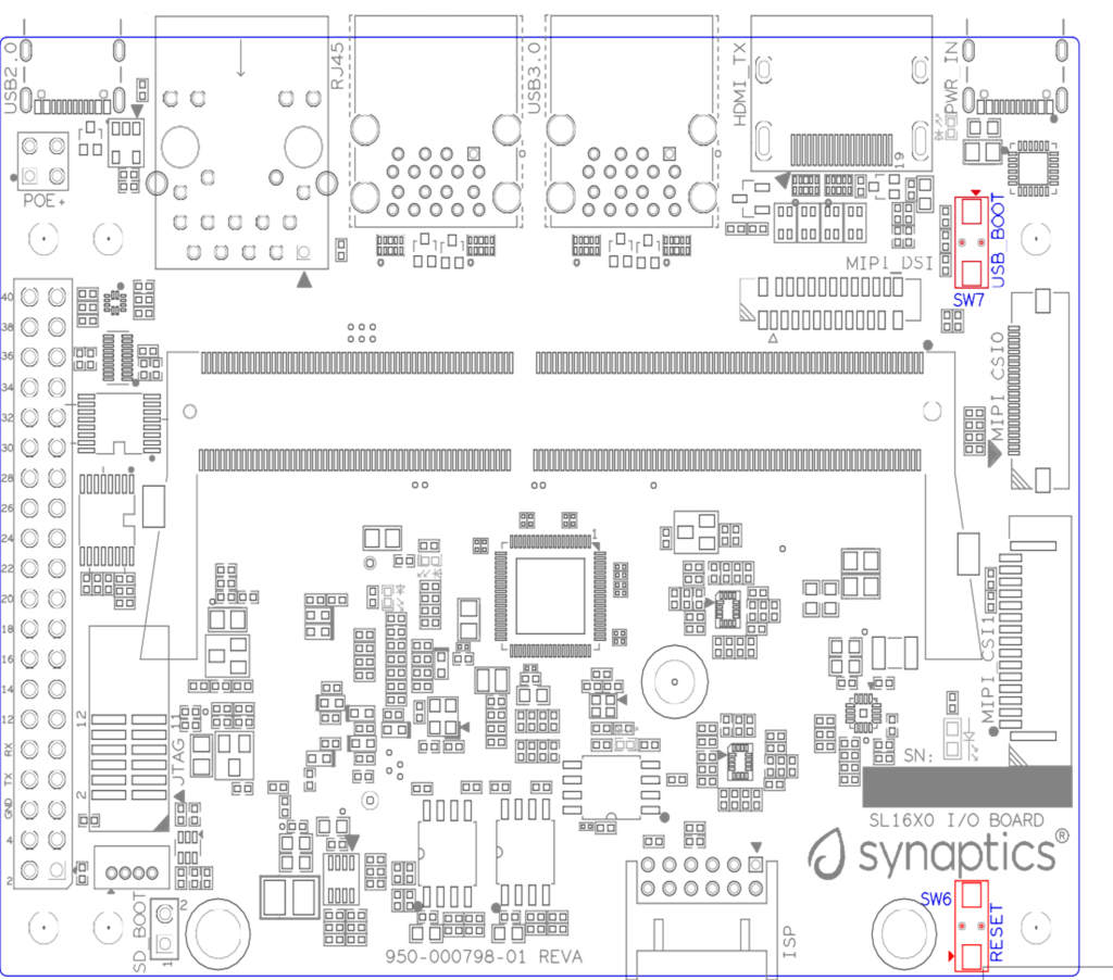
Locations of manual buttons on I/O board
Hardware Jumper Settings
Ref Des |
Type |
Pin Connection |
Description |
|---|---|---|---|
JP1 |
2x1 2.54mm header |
1-2 |
SD_Boot selection |
|
|||
|
To enter SD-Boot mode, follow these steps.
Prior to these steps, make sure SD-Card with firmware is plugged into SD-slot on core module.
Short SD_Boot header by 2.54mm jumper-cap before power-up.
Power-up system, then boot-up from SD_Card.
Locations of jumper on I/O board shows the Header locations on the I/O board.
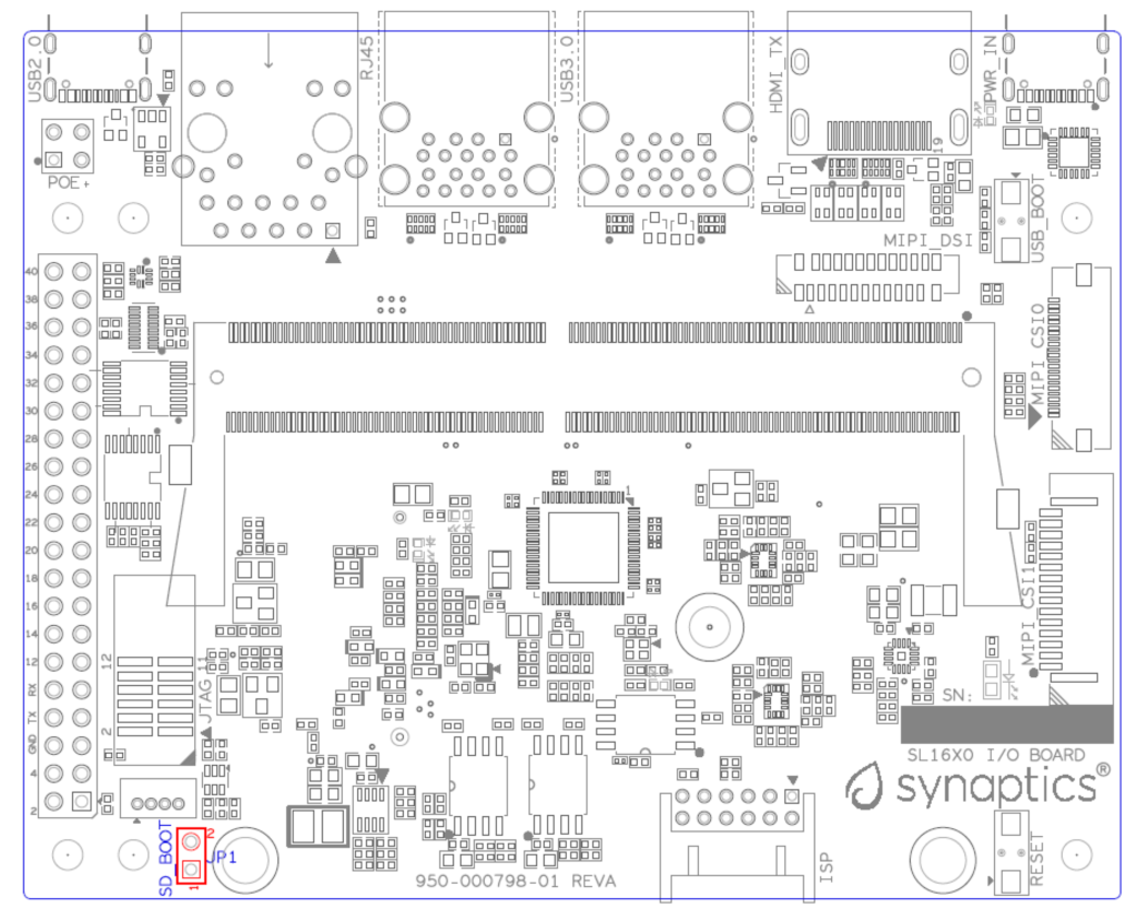
Locations of jumper on I/O board
SL1620 Evaluation System Connectors
Locations of core module connectors on top side

Locations on core module top side
Locations of core module connectors on bottom side

Locations on core module bottom side
Core module connector definitions
Main |
Connecting Boards/Devices (Ref Des if any) |
Functions |
Remarks |
|---|---|---|---|
Ref Des |
|||
J31 |
MicroSD Card |
SDIO card |
For micro-SD type of memory card extension. |
J35 |
LCD |
LCD |
Connects LCD panel daughter card through 54-pin FPC cable. |
J37 |
Line out |
Analog audio L/R |
Audio L/R output to 3.5mm Jack. |
U2, U3 |
DMIC_L/R |
PDM |
Digital MIC_L/R input. |
Locations of I/O board connectors on top side

Locations on I/O board top side
Locations of I/O board connectors on bottom side

Locations on I/O board bottom side
I/O board connector definitions
Main |
Connecting Boards/Devices (Ref Des if any) |
Functions |
Remarks |
|---|---|---|---|
Ref Des |
|||
J1 |
ISP D/C |
SPI |
12-pin daughter card to support offline program SPI NOR flash on core-module |
J2 |
RJ45 cable |
Giga Ethernet |
For Wired Ethernet connection |
J12 |
HDMI Sink |
HDMI TX |
Not applicable for SL1620. |
J13 |
FAN |
Heat Dissipation w/ FAN |
Active FAN with PWM |
J17 |
M.2 2230 D/C |
SDIO and PCIe |
1x1/2x2 WiFi/Bluetooth card via SDIO PCIe is not applicable for SL1620. |
J22 |
Debug Board |
JTAG |
XDB debugger for debugging |
J32 |
40-pins Header |
UART, I2C, SPI, PDM, I2SI/O, GPIOs, STS1, PWMs, ADC |
Flexible for support various D/C |
J34 |
PoE+ D/C |
PoE+ |
4-pin PoE+ daughter card with supporting an add-on 5V voltage to 40pin Header. |
J206 |
MIPI-CSI0 adaptor |
MIPI-CSI |
Not Applicable for SL1620 |
J207 |
MIPI-CSI1 adaptor |
MIPI-CSI |
Not Applicable for SL1620 |
J208 |
MIPI-DSI adaptor |
MIPI-DSI |
For MIPI-DSI x4 lane extension, like panel |
J210 |
USB Device |
USB 3.0 x2 |
For USB3.0 extension in Device mode only |
J213 |
TypeC power source |
Power Supply |
Power for Astra Machina rated at 15V/1.8A |
J215 |
USB Device |
USB2.0 OTG |
For USB2.0 extension, in either Host or Device mode |
J216 |
USB Device |
USB 3.0 x2 |
For USB3.0 extension in Device mode only |
Daughter Cards
A set of daughter cards supplements the Astra Machina system with a variety of I/O peripheral functionalities. Perspective devices offered by different manufacturers for each of such I/O may be implemented using respective daughter card.
Debug Board
Debug board (Rev5) allows users to communicate with the SL1620 system over JTAG through a debugger on a PC host. While connecting the evaluation system and debug board with a 20-pin flat cable, align pin-1 of the 2x10 cable socket at debug board side with pin-1 of 2x6 header J22 on the evaluation system.
Note
Users may communicate with SL1620 over UART on a PC host by using a low-cost UART to USB cable commonly available. See Astra Machina webpage for a qualified list. As an option, the debug board also provides such bridging function based on the Silicon Labs CP2102. A virtual COM port driver is required, and can be downloaded from the vendor website and installed in the PC host
UART on the evaluation system and the PC host USB are digitally isolated, with no direct conductive path, eliminating ground loop and back-drive issues when either is powered down.
Debug board connectivity for UART and JTAG shows debug board connectivity facilitating UART and JTAG communications.

Debug board connectivity for UART and JTAG
M.2 Card
An M.2 E-Key socket J17, is provided for a variety of modules in the M.2 form factor. Typical applicable modules support WiFi/BT devices with SDIO or PCIE signal interfaces.
Available modules:
Ampak AP12611_M2 with SYN43711 WiFi6E/BT5.3 1x1 over SDIO on M.2 adaptor
260-Pins SODIMM definition
A 260-Pins SODIMM connector (PN: TE_2309413-1) joins the core module and the I/O board. 260-pins SODIMM definition shows the assignment for the 260-Pins.
Assignment |
Pin# |
260-Pins SODIMM |
Pin# |
Assignment |
|---|---|---|---|---|
GePHY_RSTn (From IO_Exp) |
2 |
1 |
n/a |
|
SPI1_SDO && STRP[SS2] |
4 |
3 |
n/a |
|
SPI1_SCLK && STRP[SS3] |
6 |
5 |
n/a |
|
LCD_RSTn (From IO_EXP) |
8 |
7 |
n/a |
|
n/a |
10 |
9 |
n/a |
|
SPI1_SDI |
12 |
11 |
n/a |
|
SPI1_SS0n |
14 |
13 |
n/a |
|
External_Boot_SRC0 |
16 |
15 |
n/a |
|
USB-C_Logic_INTn |
18 |
17 |
n/a |
|
SD-CARD_PPWR_EN |
20 |
19 |
n/a |
|
SD-CARD_VIO_SEL |
22 |
21 |
n/a |
|
LCD_TP_IRQ |
24 |
23 |
n/a |
|
GND |
26 |
25 |
n/a |
|
n/a |
28 |
27 |
n/a |
|
n/a |
30 |
29 |
n/a |
|
GND |
32 |
31 |
n/a |
|
n/a |
34 |
33 |
n/a |
|
n/a |
36 |
35 |
n/a |
|
GND |
38 |
37 |
n/a |
|
n/a |
40 |
39 |
n/a |
|
n/a |
42 |
41 |
n/a |
|
GND |
44 |
43 |
n/a |
|
USB2_Dn |
46 |
45 |
n/a |
|
USB2_Dp |
48 |
47 |
n/a |
|
GND |
50 |
49 |
n/a |
|
USB3_RXp |
52 |
51 |
n/a |
|
USB3_RXn |
54 |
53 |
GND |
|
GND |
56 |
55 |
n/a |
|
USB3_TXp |
58 |
57 |
n/a |
|
USB3_TXn |
60 |
59 |
GND |
|
GND |
62 |
61 |
n/a |
|
USB3_USB20.Dp |
64 |
63 |
n/a |
|
USB3_USB20.Dn |
66 |
65 |
GND |
|
GND |
68 |
67 |
n/a |
|
USB2_IDPIN |
70 |
69 |
n/a |
|
PWR_OTG_VBUS |
72 |
71 |
GND |
|
PWR_USB3_VBUS |
74 |
73 |
n/a |
|
I2S3_BCLK |
76 |
75 |
n/a |
|
I2S3_DI |
78 |
77 |
GND |
|
I2S3_DO |
80 |
79 |
n/a |
|
2S3_LRCK |
82 |
81 |
n/a |
|
I2S1_DI |
84 |
83 |
GND |
|
GPIO[22] |
86 |
85 |
n/a |
|
PDM_DI[1] |
88 |
87 |
n/a |
|
PDM_CLKIO |
90 |
89 |
GND |
|
TW1_SCL |
92 |
91 |
n/a |
|
TW1_SDA |
94 |
93 |
n/a |
|
GPIO-EXP_0_2 |
96 |
95 |
GND |
|
FAN_TACH_Control |
98 |
97 |
n/a |
|
n/a |
100 |
99 |
n/a |
|
FAN_PWM |
102 |
101 |
GND |
|
I2S1_BCLK |
104 |
103 |
n/a |
|
EXPANDER_INT-REQn |
106 |
105 |
n/a |
|
BOOT_SRC1 |
108 |
107 |
GND |
|
I2S1_DO0 |
110 |
109 |
n/a |
|
I2S1_MCLK |
112 |
111 |
n/a |
|
I2S1_LRCK |
114 |
113 |
GND |
|
PWM2 |
116 |
115 |
MIPI_DSI_TD0n |
|
GPIO[2] |
118 |
117 |
MIPI_DSI_TD0p |
|
URT0_TXD |
120 |
119 |
GND |
|
URT0_RXD |
122 |
121 |
MIPI_DSI_TD1n |
|
SPI2_SDI |
124 |
123 |
MIPI_DSI_TD1p |
|
SPI2_SCLK |
126 |
125 |
GND |
|
SPI2_SDO |
128 |
127 |
MIPI_DSI_TCKp |
|
SPI2_SS3n |
130 |
129 |
MIPI_DSI_TCKn |
|
USB2_OCn |
132 |
131 |
GND |
|
SPI2_SS1n |
134 |
133 |
MIPI_DSI_TD3n |
|
SPI2_SS0n |
136 |
135 |
MIPI_DSI_TD3p |
|
TW1_SDA |
138 |
137 |
GND |
|
TW1_SCL |
140 |
139 |
MIPI_DSI_TD2p |
|
n/a |
142 |
141 |
MIPI_DSI_TD2n |
|
n/a |
144 |
143 |
GND |
|
SPI2_SDO_3V3 |
146 |
145 |
GND |
|
SPI2_SDI_3V3 |
148 |
147 |
n/a |
|
SPI2_CLK_3V3 |
150 |
149 |
n/a |
|
n/a |
152 |
151 |
GND |
|
USB-C_Logic_INTn |
154 |
153 |
n/a |
|
n/a |
156 |
155 |
n/a |
|
n/a |
158 |
157 |
GND |
|
Levershift_EN# for 40P header |
160 |
159 |
n/a |
|
n/a |
162 |
161 |
n/a |
|
RSTIn@PU |
164 |
163 |
GND |
|
JTAG_TDO |
166 |
165 |
n/a |
|
JTAG_TDI.SoC_WakeUp# |
168 |
167 |
n/a |
|
JTAG_TMS |
170 |
169 |
GND |
|
n/a |
172 |
171 |
n/a |
|
n/a |
174 |
173 |
n/a |
|
GPIO[48] |
176 |
175 |
GND |
|
TW2_SDA |
178 |
177 |
n/a |
|
TW2_SCL |
180 |
179 |
JTAG_TCK |
|
TW0_SDA |
182 |
181 |
GPIO[47] |
|
TW0_SCL |
184 |
183 |
JTAG_TRSTn |
|
URT1A_CTSn for M.2 |
186 |
185 |
GPIO-EXP_0_7 |
|
URT1A_RTSn for M.2 |
188 |
187 |
URT1A_RXD for M.2 |
|
PWM1 |
190 |
189 |
GPIO[55] |
|
GND |
192 |
191 |
URT1A_TXD for M.2 |
|
PWR_1V8 |
194 |
193 |
n/a |
|
PWR_1V8 |
196 |
195 |
n/a |
|
PWR_1V8_CTL |
198 |
197 |
n/a |
|
PWR_1V8_CTL |
200 |
199 |
n/a |
|
PWR_3V3_CTL |
202 |
201 |
n/a |
|
PWR_3V3_CTL |
204 |
203 |
n/a |
|
GND |
206 |
205 |
USB_BOOTn |
|
M.2_WIFI_SDIO_CLK |
208 |
207 |
SDIO_MUX_SEL (From IO_EXP) |
|
GND |
210 |
209 |
ETHERNET_LINK_LED |
|
M.2_WIFI_SDIO_CMD |
212 |
211 |
ETHERNET_DUPLX_LED |
|
GND |
214 |
213 |
GND |
|
M.2_WIFI_SDIO_D0 |
216 |
215 |
RJ45_MDIP0 |
|
GND |
218 |
217 |
RJ45_MDIN0 |
|
M.2_WIFI_SDIO_D1 |
220 |
219 |
GND |
|
GND |
222 |
221 |
RJ45_MDIP1 |
|
M.2_WIFI_SDIO_D2 |
224 |
223 |
RJ45_MDIN1 |
|
GND |
226 |
225 |
GND |
|
M.2_WIFI_SDIO_D3 |
228 |
227 |
RJ45_MDIP2 |
|
GND |
230 |
229 |
RJ45_MDIN2 |
|
PWR_3V3 |
232 |
231 |
GND |
|
PWR_3V3 |
234 |
233 |
RJ45_MDIP3 |
|
PWR_3V3 |
236 |
235 |
RJ45_MDIN3 |
|
PWR_3V3 |
238 |
237 |
GND |
|
PWR_3V3 |
240 |
239 |
PWR_BL for LCD backlight |
|
PWR_3V3 |
242 |
241 |
PWR_BL for LCD backlight |
|
GND |
244 |
243 |
GND |
|
GND |
246 |
245 |
GND |
|
GND |
248 |
247 |
GND |
|
GND |
250 |
249 |
GND |
|
PWR_5V |
252 |
251 |
PWR_5V |
|
PWR_5V |
254 |
253 |
PWR_5V |
|
PWR_5V |
256 |
255 |
PWR_5V |
|
PWR_5V |
258 |
257 |
PWR_5V |
|
PWR_5V |
260 |
259 |
PWR_5V |
40-Pins Header
A 40-pin GPIO header with 0.1-inch (2.54mm) pin pitch is on the top edge of the I/O board. Any of the general-purpose 3.3V pins can be configured in software with a variety of alternative functions. For more information, please refer to the SL1620 Datasheet.
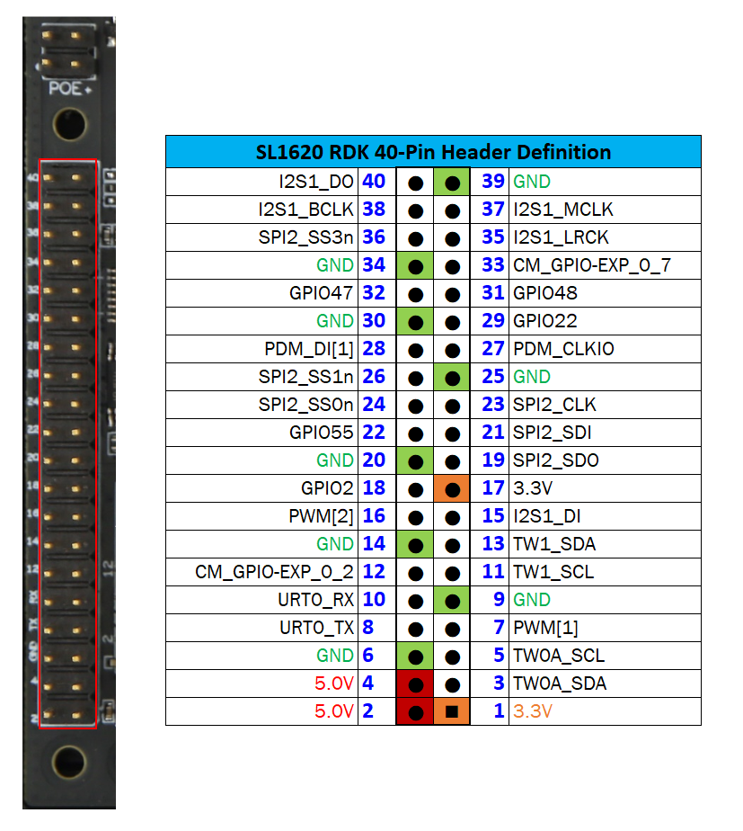
40-pin header definition
Pin-demuxing for Standard Interface Configuration
This section covers pin-demuxing configuration for the SL1620 evaluation system. For System on Chip (SoC), see SoC pin-demuxing usage.
SL1620 System-on-chip (SoC) Domain |
||||
|---|---|---|---|---|
Pad/Pin Name |
Default Usage |
Direction |
Mode Setting |
|
SDIO |
SDIO_CDn |
I:SDIOA_CDn |
IN |
MODE_1 |
SDIO_WP |
IO:GPIO[55] |
IN/OUT |
MODE_0 |
|
SPI1 |
SPI1_SS0n |
O:SPI1_SS0n |
OUT |
MODE_0 |
SPI1_SS1n |
IO:GPIO[4] |
IN |
MODE_2 |
|
SPI1_SS2n |
I:URT0A_RXD |
IN |
MODE_0 |
|
SPI1_SS3n |
O:URT0A_TXD |
OUT |
MODE_0 |
|
SPI1_SDO |
O:SPI1_SDO |
OUT |
MODE_0 |
|
SPI1_SDI |
I:SPI1_SDI |
IN |
MODE_0 |
|
SPI1_SCLK |
O:SPI1_SCLK |
OUT |
MODE_0 |
|
SPI2 |
SPI2_SS0n |
O:SPI2_SS0n |
OUT |
MODE_1 |
SPI2_SS1n |
O:SPI2_SS1n |
OUT |
MODE_1 |
|
SPI2_SS2n |
O:SPI2_SS2n |
OUT |
MODE_2 |
|
SPI2_SS3n |
O:SPI2_SS3n |
OUT |
MODE_2 |
|
SPI2_SDO |
O:SPI2_SDO |
OUT |
MODE_1 |
|
SPI2_SDI |
I:SPI2_SDI |
IN |
MODE_1 |
|
SPI2_SCLK |
O:SPI2_SCLK |
OUT |
MODE_1 |
|
UART |
URT1_RXD |
I:URT1A_RXD |
IN |
MODE_2 |
URT1_TXD |
O:URT1A_TXD |
OUT |
MODE_2 |
|
TWSI |
TW0_SCL |
IO:TW0A_SCL |
OUT |
MODE_0 |
TW0_SDA |
IO:TW0A_SDA |
IN/OUT |
MODE_0 |
|
TW1_SCL |
IO:TW1_SCL |
OUT |
MODE_0 |
|
TW1_SDA |
IO:TW1_SDA |
IN/OUT |
MODE_0 |
|
TW2_SCL |
IO:TW2_SCL |
OUT |
MODE_1 |
|
TW2_SDA |
IO:TW2_SDA |
IN/OUT |
MODE_1 |
|
TW3_SCL |
O:URT1A_RTSn |
OUT |
MODE_2 |
|
TW3_SDA |
I:URT1A_CTSn |
IN |
MODE_2 |
|
USB2 |
USB2_DRV_VBUS |
O:GPIO[51] |
OUT |
MODE_1 |
PWM |
PWM[0] |
O:PWM[0] |
OUT |
MODE_1 |
PWM[1] |
O:PWM[1] |
OUT |
MODE_1 |
|
PWM[2] |
O:PWM[2] |
OUT |
MODE_1 |
|
PWM[3] |
O:PWM[3] |
OUT |
MODE_1 |
|
RGMII |
RGMII_TXC |
O:RGMII_TXC |
OUT |
MODE_1 |
RGMII_TXD[0] |
O:RGMII_TXD[0] |
OUT |
MODE_1 |
|
RGMII_TXD[1] |
O:RGMII_TXD[1] |
OUT |
MODE_1 |
|
RGMII_TXD[2] |
O:RGMII_TXD[2] |
OUT |
MODE_1 |
|
RGMII_TXD[3] |
O:RGMII_TXD[3] |
OUT |
MODE_1 |
|
RGMII_TXCTL |
O:RGMII_TXCTL |
OUT |
MODE_1 |
|
RGMII_RXC |
I:RGMII_RXC |
IN |
MODE_1 |
|
RGMII_RXD[0] |
I:RGMII_RXD[0] |
IN |
MODE_1 |
|
RGMII_RXD[1] |
I:RGMII_RXD[1] |
IN |
MODE_1 |
|
RGMII_RXD[2] |
I:RGMII_RXD[2] |
IN |
MODE_1 |
|
RGMII_RXD[3] |
I:RGMII_RXD[3] |
IN |
MODE_1 |
|
RGMII_RXCTL |
I:RGMII_RXCTL |
IN |
MODE_1 |
|
I2S1 |
I2S1_DO |
O:I2S1_DO |
OUT |
MODE_1 |
I2S1_DI |
I:I2S1_DI |
IN |
MODE_1 |
|
I2S1_LRCK |
IO:I2S1_LRCK |
IN/OUT |
MODE_1 |
|
I2S1_BCLK |
IO:I2S1_BCLK |
IN/OUT |
MODE_1 |
|
I2S1_MCLK |
IO:I2S1_MCLK |
OUT |
MODE_1 |
|
I2S2 |
I2S2_DO |
O:I2S2_DO |
OUT |
MODE_1 |
I2S2_DI |
IO:GPIO[22] |
IN/OUT |
MODE_0 |
|
I2S2_LRCK |
IO:I2S2_LRCK |
IN/OUT |
MODE_1 |
|
I2S2_BCLK |
IO:I2S2_BCLK |
IN/OUT |
MODE_1 |
|
I2S3 |
I2S3_DO |
O:I2S3_DO |
OUT |
MODE_1 |
I2S3_DI |
I:I2S3_DI |
IN |
MODE_1 |
|
I2S3_LRCK |
IO:I2S3_LRCK |
IN/OUT |
MODE_1 |
|
I2S3_BCLK |
IO:I2S3_BCLK |
IN/OUT |
MODE_1 |
|
PDM |
PDM_CLKIO |
IO:PDM_CLKIO |
OUT |
MODE_1 |
PDM_DI[0] |
I:PDM_DI[0] |
IN |
MODE_1 |
|
PDM_DI[1] |
I:PDM_DI[1] |
IN |
MODE_1 |
|
JTAG |
TMS |
IO:GPIO[0] |
IN |
MODE_1 |
TDI |
IO:GPIO[1] |
IN |
MODE_1 |
|
TDO |
IO:GPIO[2] |
IN/OUT |
MODE_1 |
|
GPIO_A |
GPIO_A[0] |
IO:RGMIIA_MDIO |
IN/OUT |
MODE_1 |
GPIO_A[1] |
O:RGMIIA_MDC |
OUT |
MODE_1 |
|
GPIO_A[2] |
IO:GPIO[48] |
IN/OUT |
MODE_0 |
|
GPIO_A[3] |
IO:GPIO[47] |
IN/OUT |
MODE_0 |
|
NAND |
NFALE |
O:NFALE |
OUT |
MODE_1 |
NFLCS |
O:NFLCS |
OUT |
MODE_1 |
|
LCDC |
LCDD0 |
IO:LCDD0 |
IN/OUT |
MODE_1 |
LCDD1 |
IO:LCDD1 |
IN/OUT |
MODE_1 |
|
LCDD2 |
IO:LCDD2 |
IN/OUT |
MODE_1 |
|
LCDD3 |
IO:LCDD3 |
IN/OUT |
MODE_1 |
|
LCDD4 |
IO:LCDD4 |
IN/OUT |
MODE_1 |
|
LCDD5 |
IO:LCDD5 |
IN/OUT |
MODE_1 |
|
LCDD6 |
IO:LCDD6 |
IN/OUT |
MODE_1 |
|
LCDD7 |
IO:LCDD7 |
IN/OUT |
MODE_1 |
|
LCDD8 |
IO:LCDD8 |
IN/OUT |
MODE_1 |
|
LCDD9 |
IO:LCDD9 |
IN/OUT |
MODE_1 |
|
LCDD10 |
IO:LCDD10 |
IN/OUT |
MODE_1 |
|
LCDD11 |
IO:LCDD11 |
IN/OUT |
MODE_1 |
|
LCDD12 |
IO:LCDD12 |
IN/OUT |
MODE_1 |
|
LCDD13 |
IO:LCDD13 |
IN/OUT |
MODE_1 |
|
LCDD14 |
IO:LCDD14 |
IN/OUT |
MODE_1 |
|
LCDD15 |
IO:LCDD15 |
IN/OUT |
MODE_1 |
|
LCDD16 |
IO:LCDD16 |
IN/OUT |
MODE_1 |
|
LCDD17 |
IO:LCDD17 |
IN/OUT |
MODE_1 |
|
LCDD18 |
IO:LCDD18 |
IN/OUT |
MODE_1 |
|
LCDD19 |
IO:LCDD19 |
IN/OUT |
MODE_1 |
|
LCDD20 |
IO:LCDD20 |
IN/OUT |
MODE_1 |
|
LCDD21 |
IO:LCDD21 |
IN/OUT |
MODE_1 |
|
LCDD22 |
IO:LCDD22 |
IN/OUT |
MODE_1 |
|
LCDD23 |
IO:LCDD23 |
IN/OUT |
MODE_1 |
|
LPCLK |
O:LPCLK |
OUT |
MODE_1 |
|
LCDGPIO0 |
O:LCDGPIO0 |
OUT |
MODE_1 |
|
LCDGPIO1 |
O:LCDGPIO1 |
OUT |
MODE_1 |
|
LCDGPIO2 |
O:LCDGPIO2 |
OUT |
MODE_1 |
|
LCDGPIO3 |
O:LCDGPIO3 |
OUT |
MODE_1 |
Pin-demuxing for GPIO/GPO Configuration
This section covers pin-demuxed GPIO/GPO usage of SoC domains.
SL1620 SoC |
Availability |
Direction |
Default Function |
GPIO Signaling |
|---|---|---|---|---|
GPIO/GPO |
||||
GPIO[0] |
MODE_1 |
IN |
GPIO_EXP_INTn (CM) |
0: GPIO Expander triggers interrupt (Core Module) |
1: No interrupt |
||||
GPIO_X[0] |
Not Available |
IN/OUT |
IO:LCDD8 |
— |
GPIO[1] |
MODE_1 |
IN |
WiFi_WAKE_UP# |
0: Wake up triggered by WiFi |
1: No wake up trigger |
||||
GPIO_X[1] |
Not Available |
IN/OUT |
IO:LCDD9 |
— |
GPIO[2] |
MODE_1 |
IN/OUT |
IO:LCDD16 |
To 40-Pin header |
GPIO_X[2] |
Not Available |
IN/OUT |
O:SM_FE_LED[0] |
— |
GPIO[3] |
Not Available |
OUT |
O:SPI1_SS0n |
— |
GPIO[4] |
MODE_2 |
IN |
GPIO_EXP_INTn (I/O Board) |
0: GPIO Expander triggers interrupt (I/O Board) |
1: No interrupt |
||||
GPIO[5] |
MODE_0 |
IN |
I:URT0A_RXD |
To 40-Pin header |
GPIO[6] |
MODE_0 |
OUT |
O:URT0A_TXD |
To 40-Pin header |
GPO[7] |
Not Available |
OUT |
O:SPI1_SDO |
— |
GPO[8] |
Not Available |
OUT |
O:SPI1_SCLK |
— |
GPIO[9] |
Not Available |
IN |
I:SPI1_SDI |
— |
GPIO[10] |
MODE_0 |
OUT |
IO:TW0A_SCL |
To 40-Pin Header/ Display IF/ GPIO_EXP_CM |
GPIO_X[10] |
Not Available |
IN/OUT |
O:LCDGPIO3 |
— |
GPIO[11] |
MODE 0 |
IN/OUT |
IO:TW0A_SDA |
To 40-Pin Header/ Display IF/ GPIO_EXP_CM |
GPIO_X[11] |
MODE 0 |
IN |
GePHY_INTB |
0: Interrupt is triggered by GePHY |
1: No interrupt |
||||
GPIO[12] |
MODE_0 |
OUT |
IO:TW1_SCL |
To 40-Pin Header/ M.2/ GPIO_EXP_IO |
GPIO_X[12] |
Not Available |
IN/OUT |
IO:LCDD0 |
— |
GPIO[13] |
MODE_0 |
IN/OUT |
IO:TW1_SDA |
To 40-Pin Header/ M.2/ GPIO_EXP_IO |
GPIO_X[13] |
Not Available |
IN/OUT |
IO:LCDD1 |
— |
GPIO[14] |
MODE_1 |
OUT |
IO:I2S1_LRCK |
To 40-Pin Header |
GPIO_X[14] |
Not Available |
IN/OUT |
IO:LCDD23 |
— |
GPIO[15] |
MODE_1 |
OUT |
IO:I2S1_BCLK |
To 40-Pin Header |
GPIO_X[15] |
Not Available |
OUT |
O:LPCLK |
— |
GPO[16] |
MODE_1 |
OUT |
O:I2S1_DO |
To 40-Pin Header |
GPIO_X[16] |
Not Available |
OUT |
O:LCDGPIO0 |
— |
GPIO[17] |
MODE_1 |
OUT |
IO:I2S1_MCLK |
To 40-Pin Header |
GPIO_X[17] |
Not Available |
OUT |
O:LCDGPIO1 |
— |
GPIO[18] |
MODE_1 |
IN |
I:I2S1_DI |
To 40-Pin Header |
GPIO_X[18] |
Not Available |
OUT |
O:LCDGPIO2 |
— |
GPIO[19] |
Not Available |
OUT |
IO:I2S2_LRCK |
— |
GPIO_X[19] |
Not Available |
OUT |
O:RGMII_TXD[0] |
— |
GPIO[20] |
Not Available |
OUT |
IO:I2S2_BCLK |
— |
GPIO_X[20] |
Not Available |
OUT |
O:RGMII_TXD[1] |
— |
GPO[21] |
Not Available |
OUT |
O:I2S2_DO |
— |
GPIO_X[21] |
Not Available |
OUT |
O:RGMII_TXD[2] |
— |
GPIO[22] |
MODE_0 |
IN/OUT |
IO:GPIO[22] |
To 40-Pin Header |
GPIO_X[22] |
Not Available |
OUT |
O:RGMII_TXD[3] |
— |
GPIO[23] |
MODE_1 |
IN |
I:PDM_DI[1] |
To 40-Pin Header |
GPIO[24] |
Not Available |
IN |
I:PDM_DI[0] |
— |
GPIO[25] |
MODE_1 |
OUT |
IO:PDM_CLKIO |
To 40-Pin Header/ DMIC on Board |
GPIO[26] |
Not Available |
OUT |
IO:I2S3_LRCK |
— |
GPIO[27] |
Not Available |
OUT |
IO:I2S3_BCLK |
— |
GPO[28] |
Not Available |
OUT |
O:I2S3_DO |
— |
GPIO[29] |
Not Available |
IN |
I:I2S3_DI |
— |
GPO[30] |
MODE_1 |
OUT |
O:SPI2_SS0n |
To 40-Pin Header |
GPIO[31] |
MODE_1 |
OUT |
O:SPI2_SS1n |
To 40-Pin Header |
GPIO_X[31] |
Not Available |
IN |
I:RGMII_RXD[0] |
— |
GPIO[32] |
Not Available |
OUT |
O:SPI2_SS2n |
— |
GPIO_X[32] |
Not Available |
IN |
I:RGMII_RXD[1] |
— |
GPIO[33] |
MODE_2 |
OUT |
O:SPI2_SS3n |
To 40-Pin Header |
GPIO_X[33] |
Not Available |
IN |
I:RGMII_RXD[2] |
— |
GPO[34] |
MODE_1 |
OUT |
O:SPI2_SDO |
To 40-Pin Header/ LCDC |
GPO[35] |
MODE_1 |
OUT |
O:SPI2_SCLK |
To 40-Pin Header/ LCDC |
GPIO[36] |
MODE_1 |
IN |
I:SPI2_SDI |
To 40-Pin Header/ LCDC |
GPIO[37] |
Not Available |
OUT |
IO:TW2_SCL |
— |
GPIO[38] |
Not Available |
IN/OUT |
IO:TW2_SDA |
— |
GPIO[39] |
Not Available |
IN |
I:URT1A_RXD |
— |
GPIO_X[39] |
Not Available |
IN/OUT |
IO:LCDD17 |
— |
GPIO[40] |
Not Available |
OUT |
O:URT1A_TXD |
— |
GPIO_X[40] |
Not Available |
IN/OUT |
IO:LCDD22 |
— |
GPIO[41] |
Not Available |
OUT |
O:URT1A_RTSn |
— |
GPIO_X[41] |
Not Available |
IN |
I:RGMII_RXD[3] |
— |
GPIO[42] |
Not Available |
IN |
I:URT1A_CTSn |
— |
GPIO_X[42] |
Not Available |
IN |
I:RGMII_RXC |
— |
GPIO[43] |
Not Available |
OUT |
O:PWM[3] |
— |
GPIO_X[43] |
Not Available |
OUT |
O:RGMII_TXC |
— |
GPIO[44] |
MODE_1 |
OUT |
O:PWM[2] |
To 40-Pin Header |
GPIO[45] |
MODE_1 |
OUT |
O:PWM[1] |
To 40-Pin Header |
GPO[46] |
Not Available |
OUT |
O:PWM[0] |
— |
GPIO[47] |
MODE_0 |
IN/OUT |
IO:GPIO[47] |
To 40-Pin Header |
GPIO[48] |
MODE_0 |
IN/OUT |
IO:GPIO[48] |
To 40-Pin Header |
GPIO[49] |
Not Available |
OUT |
O:RGMIIA_MDC |
— |
GPIO[50] |
Not Available |
IN/OUT |
IO:RGMIIA_MDIO |
— |
GPIO[51] |
MODE_1 |
OUT |
Audio_Mute |
0: Mute |
1: un-Mute |
||||
GPIO_X[51] |
Not Available |
OUT |
O:RGMII_TXCTL |
— |
GPIO[52] |
Not Available |
OUT |
O:NFALE |
— |
GPIO_X[52] |
Not Available |
IN |
I:RGMII_RXCTL |
— |
GPIO[53] |
Not Available |
OUT |
O:NFLCS |
— |
GPIO_X[53] |
Not Available |
IN |
O:RGMII_CLK_OUT |
— |
GPO[54] |
Not Available |
IN |
I:SDIOA_CDn |
— |
GPIO[55] |
MODE_0 |
IN/OUT |
IO:GPIO[55] |
To 40-Pin Header |
GPIO[56] |
Not Available |
IN/OUT |
IO:LCDD2 |
— |
GPIO[57] |
Not Available |
IN/OUT |
IO:LCDD3 |
— |
GPIO[58] |
Not Available |
IN/OUT |
IO:LCDD4 |
— |
GPIO[59] |
Not Available |
IN/OUT |
IO:LCDD5 |
— |
GPIO[60] |
Not Available |
IN/OUT |
IO:LCDD6 |
— |
GPIO[61] |
Not Available |
IN/OUT |
IO:LCDD7 |
— |
GPIO[62] |
Not Available |
IN/OUT |
IO:LCDD10 |
— |
GPIO[63] |
Not Available |
IN/OUT |
IO:LCDD11 |
— |
GPIO[64] |
Not Available |
IN/OUT |
IO:LCDD12 |
— |
GPIO[65] |
Not Available |
IN/OUT |
IO:LCDD13 |
— |
GPIO[66] |
Not Available |
IN/OUT |
IO:LCDD14 |
— |
GPIO[67] |
Not Available |
IN/OUT |
IO:LCDD15 |
— |
GPIO[68] |
Not Available |
IN/OUT |
IO:LCDD18 |
— |
GPIO[69] |
Not Available |
IN/OUT |
IO:LCDD19 |
— |
GPIO[70] |
Not Available |
IN/OUT |
IO:LCDD20 |
— |
GPIO[71] |
Not Available |
IN/OUT |
IO:LCDD21 |
— |
GPIO Expanders Over I2C
Due to the considerable number of functionalities covered by the SL1620 evaluation system, most of the SL1620 digital pins that have GPIO/GPO pin-demux options are used for other functions. As such, GPIO expanders are used extensively to supplement system control purposes.
Expander |
I2C# |
Domain |
Voltage |
Direction |
Function |
GPIO Signaling |
|---|---|---|---|---|---|---|
GPIO/GPO |
||||||
GPIO0_0 |
TW1 (0x43) |
SoC |
3.3V |
OUT |
SDIO-MUX_SEL |
0: Switch SDIO to M.2 WiFi |
1: Switch SDIO to SD Card Slot |
||||||
GPIO0_1 |
TW1 (0x43) |
SoC |
3.3V |
OUT |
PWR_ON_DSI |
0: Power OFF DSI panel |
1: Power ON DSI panel |
||||||
GPIO0_2 |
TW1 (0x43) |
SoC |
3.3V |
OUT |
LCD_RST# |
0: Reset LCD |
1: De-assert Reset |
||||||
GPIO0_3 |
TW1 (0x43) |
SoC |
3.3V |
OUT |
GePHY_RST# |
0: Reset |
1: De-assert Reset |
||||||
GPIO0_4 |
TW1 (0x43) |
SoC |
3.3V |
OUT |
STAND-BY_EN |
0: Normal playback |
1: Entry to Stand-By status with peripherals Powered down |
||||||
GPIO0_5 |
TW1 (0x43) |
SoC |
3.3V |
IN |
USB2.0_PWR_EN |
0: Power OFF |
1: Power ON |
||||||
GPIO0_6 |
TW1 (0x43) |
SoC |
3.3V |
IN |
Not used |
– |
– |
||||||
GPIO0_7 |
TW1 (0x43) |
SoC |
3.3V |
IN/OUT |
GPIO_DSI |
In reserved |
In reserved |
||||||
GPIO1_0 |
TW1 (0x44) |
SoC |
3.3V |
IN |
USB-C_Logic_INT# |
0: Status changed |
1: Status not changed |
||||||
GPIO1_1 |
TW1 (0x44) |
SoC |
3.3V |
OUT |
Not used |
– |
– |
||||||
GPIO1_2 |
TW1 (0x44) |
SoC |
3.3V |
OUT |
M2-W_DISABLE1# |
0: Disable M.2 module by DISABLE1# |
1: De-assertion |
||||||
GPIO1_3 |
TW1 (0x44) |
SoC |
3.3V |
OUT |
M2-W_HOST-WAKE# |
0: Assertion Wake-up event from Host to M.2 module |
1: De-assertion |
||||||
GPIO1_4 |
TW1 (0x44) |
SoC |
3.3V |
OUT |
SD-CARD_PWR_EN |
0: Power OFF SD card slot |
1: Power ON SD card slot |
||||||
GPIO1_5 |
TW1 (0x44) |
SoC |
3.3V |
OUT |
M2-W_DISABLE2# |
0: Disable M.2 module by DISABLE2# |
1: De-assertion |
||||||
GPIO1_6 |
TW1 (0x44) |
SoC |
3.3V |
OUT |
SD-CARD_VIO_SEL |
0: 1.8V |
1: 3.3V |
||||||
GPIO1_7 |
TW1 (0x44) |
SoC |
3.3V |
OUT |
LCD_TP_IRQ# |
0: Interrupt is triggered |
1: No interrupt |
||||||
GPIO0_0 |
TW0 (0x43) |
SoC |
1.8V |
IN |
FAN_TECH_CON |
0: Fan gets Error |
1: No interrupt |
||||||
GPIO0_1 |
TW0 (0x43) |
SoC |
1.8V |
IN |
AUD_JACK_DET |
0: Audio Jack exist |
1: No Audio Jack |
||||||
GPIO0_2 |
TW0 (0x43) |
SoC |
1.8V |
IN/OUT |
GPIO_0_2 (40-Pin Header) |
0: Depends on user definition |
1: Depends on user definition |
||||||
GPIO0_3 |
TW0 (0x43) |
SoC |
1.8V |
OUT |
NAND_WP# |
0: Write protection |
1: Write accessible |
||||||
GPIO0_4 |
TW0 (0x43) |
SoC |
1.8V |
OUT |
DMIC_MUTE# |
0: Mute DMIC |
1: De-Mute DMIC |
||||||
GPIO0_5 |
TW0 (0x43) |
SoC |
1.8V |
OUT |
LevelTranslator_EN# |
0: Enable Level translator |
1: Disable Level translator |
||||||
GPIO0_6 |
TW0 (0x43) |
SoC |
1.8V |
IN |
USB2_CONN_OC# |
0: Detect USB2 Over-Current |
1: Normal status |
||||||
GPIO0_7 |
TW0 (0x43) |
SoC |
1.8V |
IN/OUT |
GPIO_0_7 (40-Pin Header) |
0: Depends on user definition |
1: Depends on user definition |
I2C Bus
This section describes the Astra Machina’s usage of the I2C bus, the equivalence of SL1620’s Two Wire Serial Interface (TWSI) bus.
I2C/TWSI Bus |
Device |
Part Number |
Ref Des |
Target Address (7-bit) |
Location |
|---|---|---|---|---|---|
TW0 |
External device connects to MIPI_DSI connector |
Not applicable |
J208 |
0xXX |
SL16x0 I/O board |
External device connects to 40-pin Header |
Not applicable |
J32 |
0xXX |
SL16x0 I/O board |
|
External device connects to LCD connector |
Not applicable |
J35 |
0xXX |
SL1620 core module |
|
IC GPIO Expander |
FXL6408UMX |
U8 |
0x43 |
SL1620 core module |
|
TW1 |
IC GPIO Expander |
FXL6408UMX |
U12 |
0x43 |
SL16x0 I/O board |
IC GPIO Expander |
FXL6408UMX |
U13 |
0x44 |
SL16x0 I/O board |
|
External device connects to 40-pin Header |
Not applicable |
J32 |
0xXX |
SL16x0 I/O board |
|
TW2 |
IC REG, default 0.8V Vout /5mV Step, 6A rating, Input 5.5V@Max, Step-Down Convertor with I2C |
TPS628660AYCG |
U39 |
0x49 |
SL1620 core module |
Bringing Up the SL1620 Astra Machina System
Connecting External Components and Performing Hardware Testing
Perform the following steps to connect the external components to SL1620 evaluation system:
Connect a TypeC power supply to J213 (PWR_IN).
Connect MIPI_DSI daughter board with Panel through FPC cable to J208.
Connect Network to J2 (RJ45) with an Ethernet cable.
Insert USB3.0 flash disk to J216 /J210 (USB3.0).
Insert USB2.0 flash disk to J215 (USB2.0) over TypeC/TypeA dongle.
If there are no short issues, power up the system and check voltages as shown in Short and voltage check points using any test point for ground with the LED status shown in LED definitions on I/O board.

Short and voltage check points
Ref Des |
Form |
Signal |
Voltage |
|---|---|---|---|
C123 |
Pad 2 |
PWR_LCD_BL |
15V +/- 2% [14.7,15.3] |
C414 |
Pad 1 |
PWR_5V |
5.2V +/- 2% [5.096,5.304] |
C6 |
Pad 1 |
PWR_3V3 |
3.3V +/- 1% [3.267,3.333] |
Q3 |
Pad 2 |
PWR_1V8 |
1.8V +/- 2% [1.764,1.836] |
C452 |
Pad 1 |
PWR_VDDM_1V2 |
1.2V +/- 2% [1.176,1.224] |
C441 |
Pad 1 |
PWR_VDDM_2V5 |
2.5V +/- 2% [2.45,2.55] |
R554 |
Pad 2 |
PWR_VCORE_FB |
Vcore_FB +/- 2% |
References
The following documents are applicable to the SL1620 evaluation system:
SL1620 Datasheet (PN: 505-001428-01)