Astra Security
Introduction
The Astra SL16xx Secure Boot process is a multi-stage boot mechanism designed to ensure the integrity and authenticity of the firmware executed on the Astra Machina platform. It consists of the following main stages:
ROM Boot & SPK – The initial boot stage that establishes a root of trust
Pre-boot – The second stage that performs further system initialization and establish secure and nonsecure execution environment on ACPU
OS Bootloader – Customer Bootloader, such as u-boot, that runs in non-secure
Kernel and OS – Loads of the Linux Kernel and file system
Boot ROM & SPK
Astra Machina platform uses an ARM Cortex-M3 process as a dedicated security island. The boot process starts with ROM on this security island while all other CPUs remain in a reset state. The ROM code is embedded in the chip and cannot be modified. Key functions of ROM include:
Initializes the crypto engine, DMA, and other essential hardware.
Loads and authenticates RSA signing keys from the boot device
Enforces OTP-based checks and hardware-enforced protections
Loads the SPK (Secure Processor Kernel) from flash, decrypts, and verifies it.
SPK provides cryptographic services for the system, functions supported are shown in the table below.
Algorithm |
Encrypt |
Decrypt |
Key Length |
Mode |
|---|---|---|---|---|
AES |
Yes |
Yes |
128/192/256 |
ECB /CBC/CTR/XTS/GCM |
TDES |
Yes |
Yes |
56/168 |
ECB/CBC |
RC4 |
Yes |
Yes |
256 |
|
ECC |
Yes |
Yes |
224/256/384/521 |
|
RSA |
Yes |
Yes |
102 4/2048/4096/8192 |
|
SHA |
SHA-1 /SHA-224/SHA-256 /SHA-384/SHA-512 |
Astra Pre-boot
Pre-boot will initialize the basic services in secure world, performs necessary system and DDR initialization, validates the OS Bootloader image and prepare its running environment. Astra Pre-boot image is signed and encrypted using Synaptics key.
U-Boot (OS Bootloader)
Astra SDK uses U-Boot, a popular open-source bootloader, which
Loads and executes the OS kernel (Linux, RTOS, etc.) based on A/B partition selection
Handles boot sources (eMMC, SPI, NAND, SD card, USB, etc.)
Supports debugging and firmware recovery
Supports OTP programming and reading
Supports on-board image updates
In Astra SDK, U-Boot image is provided in clear mode, it is protected by ODM/OEM key after MP flow.
Linux Kernel (OS)
Once U-Boot hands over control to the Linux kernel (OS), the system goes through several critical steps to initialize hardware, set up the OS, and start user applications
Kernel Initialization
Start system services
Start user applications
In Astra SDK, Kernel image is provided in clear mode. It can be signed and encrypted by ODM/OEM key after MP flow, OPTEE can be used for decryption and authentication before Kernel loading.
Astra Security Features
SPK (Secure Processor Kernel)
A dedicated security enclave with cryptographic acceleration.
Implements runtime integrity checks to prevent code tampering.
Key Management
Uses a hierarchical key structure with root RSA keys (K0_BOOT, K0_TEE, K0_REE).
RSA keys are stored in external flash but are hash-locked in OTP to prevent unauthorized changes.
Boot Device and Failover
Supports booting from eMMC, SPI, NAND, SD, and USB.
Redundant boot partitions ensure failsafe in case of image corruption.
Security separation
ARM TrustZone – secure and non-secure worlds separation
Trusted OS – Secure world operating system
Secure Zone Controller to protect memory and peripherals configurable for per-master, secure/non-secure, read/write attributes.
True Random Number Generator (TRNG)
DDR scrambler
Keys are managed and provisioned by SPK
Debug security
JTAG protection is configurable via OTP with three levels
Open
Password protected
Close
Astra secure boot mechanism ensures that only verified and authorized firmware runs on the device, protecting it from unauthorized modifications and ensuring device integrity throughout its lifecycle.
Key Management
The SL16xx Secure Boot implements a hierarchical key management system to ensure firmware authenticity, integrity, and confidentiality. It utilizes RSA keys for authentication and AES keys for encryption. Through defined key management scheme, we ensure:
Device security and trusted boot based on Hardware Root of Trust
Only authenticated firmware runs via RSA signature verification
Firmware confidentiality is maintained through AES encryption
Security is reinforced with segmentation, version control, and OEM Signing & MP flow
RSA Key Management
Synaptics devices implement a hierarchy of signing keys that are used for authenticating all software images involved in the secure boot chain.
At the root of the hierarchy there are independent root keys which are stored in the external flash and hash-locked to their SHA-256 hash value in the OTP to make them immutable. The root keys are verified by the ROM code which establishes independent root of trust.
The root keys are not used directly; they are used to sign “level one” keys which are then used to sign the different software images.
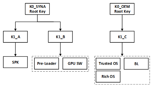
The key hierarchy
AES Key Management
Four symmetric key slots are allocated in OTP.
Key ID |
Description |
Key size (bit) |
Owner / provisioned by |
Scope |
|---|---|---|---|---|
MDK |
Master Distribution Key |
128 |
Synaptics |
Common to all chips |
CUK |
Chip Unique Key |
128 |
Synaptics |
Unique for each chip |
AESK0 |
AES key 0 |
128 |
OEM |
Common for all chips |
RKEK |
Root Key Encryption Key |
128 |
OEM |
Unique for each device |
The root keys are generated from a qualified HSM offline before being programmed into OTP.
MDK is typically used as the root key for deriving image-specific encryption key.
CUK is used as the root key for deriving chip-unique key for encrypting secure data.
AESK0 and RKEK are the counterparts of MDK and CUK and managed by OEM.
Secure Boot
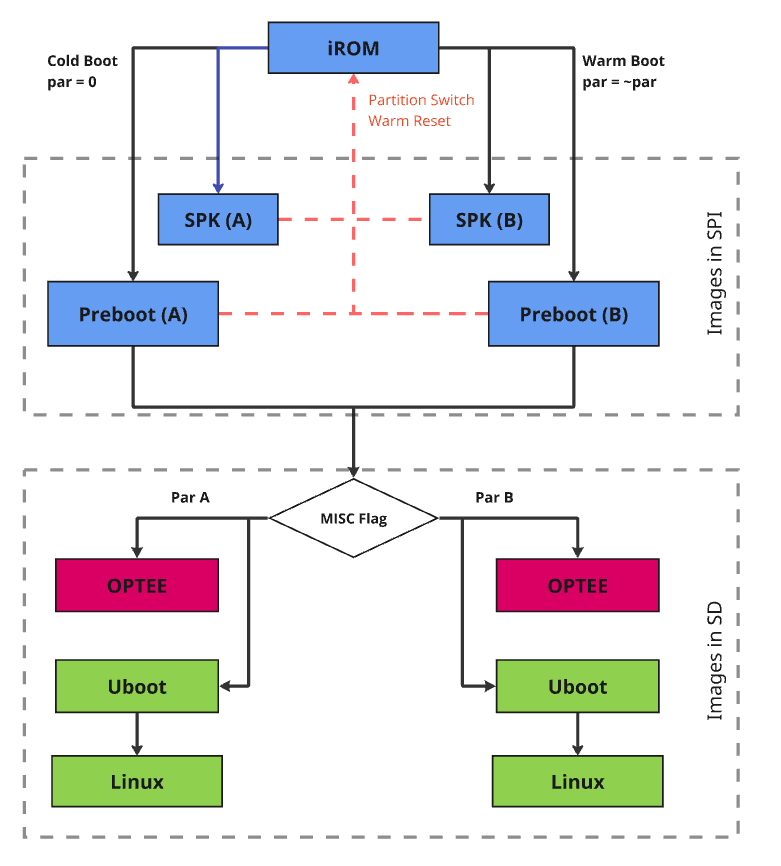
The generic secure boot flow is consistent across all Astra Machina platforms, with some differences based on the booting media. Astra supports A/B boot mechanisms for failover at multiple stages, including pre-boot, U-Boot, and the operating system. The pre-boot A/B functionality is provided by Synaptics, while the A/B boot process for U-Boot and the kernel can be customized by OEMs to suit their specific needs.
Generic Boot Flow
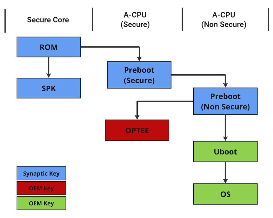
Astra Generic Boot Flow
A/B Boot Flow (boot failover)
A/B boot is a fault-tolerant boot mechanism designed to ensure system reliability during software updates. It maintains two sets of images, referred as slot A and slot B, or partition A and partition B. This allows the device to fall back to the inactive slot if the active one fails to boot. This approach also helps prevent bricking and supports seamless over-the-air (OTA) updates.
Pre-boot A/B Boot Flow
Astra Machina ROM can select the correct pre-boot image to boot based on image verification result. When active partition boot fails, device can boot from the alternative partition if contained images pass integrity checks.
User Space A/B Boot Flow
A partition flag in the boot control block in misc partition is used by pre-boot image to decide which U-boot copy to use. Similarly, U-boot checks the same boot control block to decide which Kernel image to load.
EMMC Boot
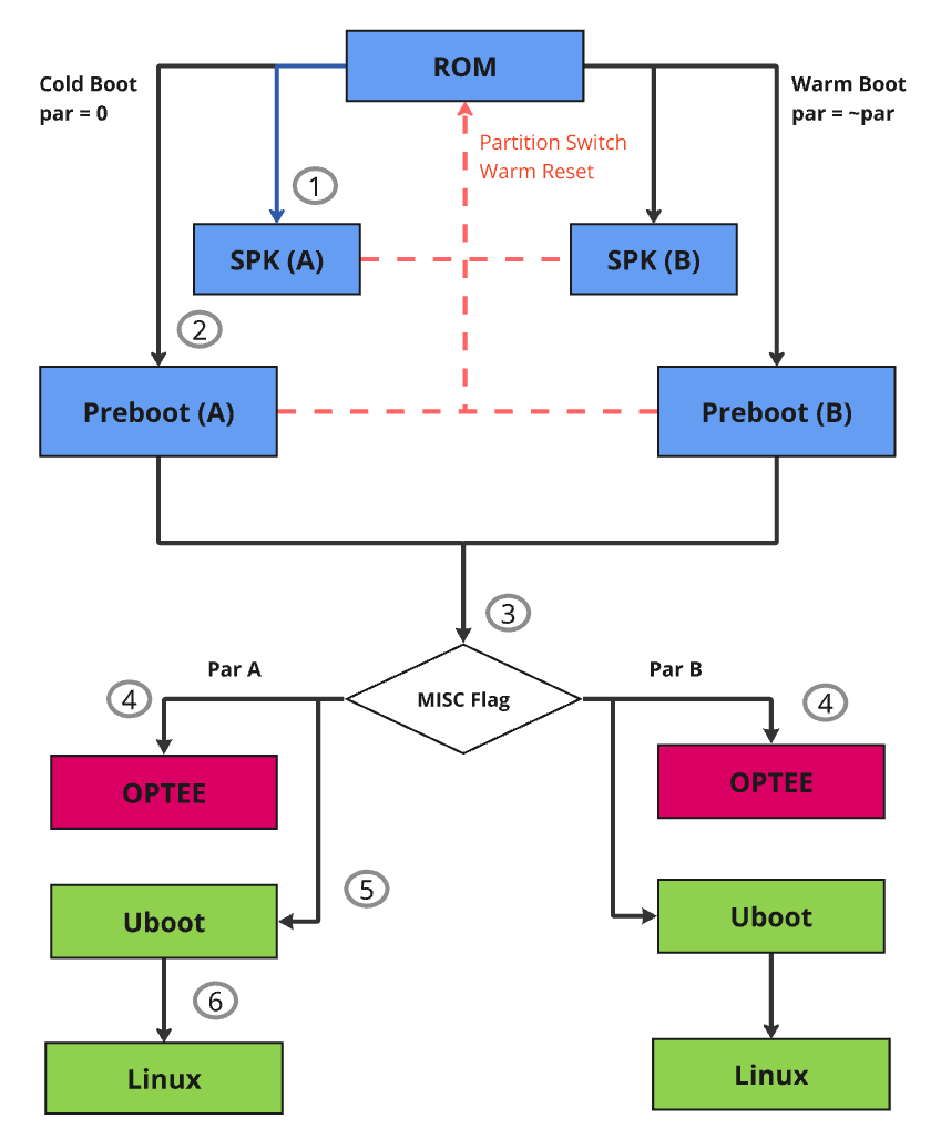
Astra eMMC Boot Flow
Boot Flow Explanation:
Upon a cold boot, ROM first verifies and sets up SPK:
SPK provides crypto functionalities to the system at later stage
SPK runs in a dedicated security domain, where only authorized security entity (such as TA) can request security services via a mailbox call
After the SPK is loaded, Pre-boot images are loaded and verified by SPK:
SPK loads and verifies the Pre-boot images which are responsible for setting up the system and environment for Secure OS and Rich OS
Any failure will trigger failsafe mechanism leading to boot attempt from other partition
The last preboot image (1st stage loader) is responsible for loading the U-Boot (2nd stage loader)
1st stage loader checks the OS-boot partition flag within the boot control block. This boot control block is located in a misc partition on the flash.
To ensure failsafe, 1st stage loader has a factory copy of the boot control block, this ensures device can continue to boot when the active boot control block is corrupted (See misc partition selection handling for details in subsection 5.2)
The 1st stage loader loads and verifies the OPTEE according to the OS boot partition flag.
With Astra SDK, OPTEE and U-Boot are in clear by default, they are only signed and encrypted if OEM security is enabled via MP flow
OPTEE lives in the secure domain of the A-CPU, often referred to as trusted execution environment (TEE).
Applications in rich execution environment (REE) can communicate with TEE through trusted application (TA)
The 1st stage loader loads and verifies U-Boot according to the OS boot partition flag.
If OEM security is enabled, U-Boot is signed and encrypted by using the OEM key
Once U-Boot is running, the trusted secure boot chain responsibility is in OEM’s hand.
The U-Boot loads and verifies kernel Image.
The kernel Image is signed and encrypted by using the OEM key, OPTEE is used to verify the image
For failsafe, OEM can use its own A/B logic or use the same OS-Boot partition flag.
If OS-Boot partition flag is used, U-Boot and kernel are always coming from the same partition because the same flag is used
SPI Boot
Astra SPI booting sequence is same as Astra eMMC Boot, please refer to Figure 3: Astra eMMC Boot Flow for details.
NAND Boot
NAND flash could have bad blocks due to manufacturing defects and wear over time. To ensure reliable booting, most NAND flash vendors guarantee that the initial few blocks are error-free.
For NAND boot, ROM reads essential information for boundary scan from block 0. In Synaptics Astra SDK, up to 8 copies of preboot images are stored starting from NAND flash block 1, by default, each copy occupies 2 flash blocks and each block is 256 Bytes (block number and block size are configurable). ROM loads SPK and preboot images based on boundary scan result and executes.
Note: Astra Machina board does not have NAND interface support; as a result, NAND boot can only be done on vendor HW device.
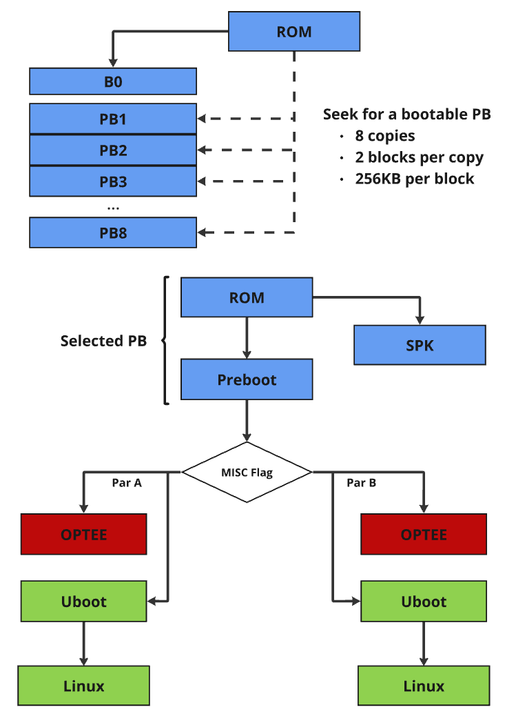
Astra NAND Boot Flow
SD Card Boot
Astra SDK SD Card boot flow is similar to Astra SPI boot. It relies on Astra Machina onboard SPI NOR to complete the Pre-boot and uses inserted SD card to complete the remaining boot process, U-boot and OS.
Astra SD Card Boot
USB Host Boot
Astra USB Host Boot uses the same boot flow without A/B. Please see Figure 2: Astra Generic Boot Flow for details.
Software Image Verification
SPK is responsible for image verification. It uses the hardware crypto engine to accelerate operations.
All software images are signed and encrypted. The image signature scheme is SHA256-RSA2048. Images are encrypted with image-specific keys derived from root symmetric key. AES-CBC is the algorithm for encryption, and the key size is 128-bit. The key derivation function (KDF) is compliant with NIST SP800-108 standard.
Trusted Execution Environment (TEE)
Architecture
The figure below depicts an example system architecture from a SoC, indicating the components that make up the Rich Execution Environment (REE) vs the components that make up the Trusted Execution Environment (TEE).
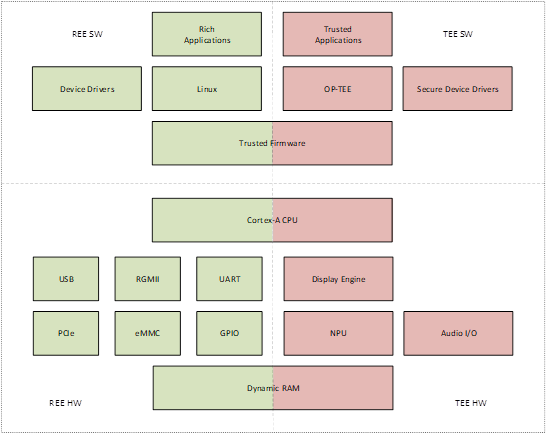
TEE architecture diagram
In this figure, the system is shown to consist of non-secure software running in the REE; secure software running in the TEE; non-secure hardware controlled by the REE; and secure hardware controlled by the TEE.
Additionally, there is some hardware which is consider both part of the REE and the TEE. The application CPU (Cortex-A class) has the capability to execute secure or non-secure workloads by means of time sharing. The Dynamic RAM is partitioned into an area which is accessible by the REE, and another area which is only accessible by the TEE.
The system can be further subdivided into different security domains based on use-cases, for example TA executes its own isolated space, which is managed by OP-TEE.
TEE Software
The software architecture of the software running on the Host CPU is depicted in the figure below, indicating the secure vs. non-secure state and exception level.
The open-source OP-TEE is integrated and serves as the Trusted-OS.
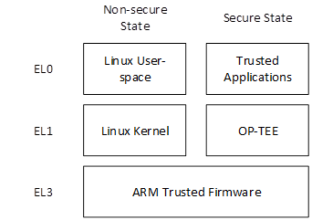
Cortex-A (ACPU) TEE software architecture
Communication from Linux User Space to a Trusted Application follows these steps:
The user-space application calls a client API, which packs the parameters into a message buffer
The user space application issues a system call to the Linux TrustZone Driver (TZD) to pass the message to the TEE
The TZD uses the SMC instruction to trap into EL3
ARM Trusted Firmware (ATF) switches the CPU to secure state and resumes TZ Kernel in Secure EL1 with the message being passed
OP-TEE locates the target Trusted Application, and switches the secure execution context to Secure EL0 in the target TA
The target TA processes the command
Trusted Application Partitioning
Each trusted application is isolated from other trusted applications and has access to its own memory space. This isolation is done using the ACPU MMU. The MMU is under the control of the OP-TEE executing in Secure EL1 and cannot be modified by trusted applications executing in Secure EL0.
TA Development
TA development follows OP-TEE specification. In Astra SDK, TA encryption
is not enabled. OEM can enable it by setting CFG_ENCRYPT_TA=y before
building OPTEE OS. For TA development and encryption, please refer to
OP-TEE document Trusted
Applications
for details.