ISP Sensor Integration Guide
Introduction
This document explains how to add a new sensor driver to the SL1680 and SL2610 platforms. Since the integration process differs between the two, refer to the appropriate section below.
Sensor Integration on SL1680
The sensor driver shall be implemented as per Application Programming Interface (API) of the Verisilicon ISP Independent Sensor Interface (ISI) framework. For more details, refer to ISI documentation.
Configuration
Adding a new sensor includes creating necessary directories, adding source and header files, configuring CMake, and updating configuration files. This requires modifying the
synasdk-v4l2isp-sensordrv and linux-syna packages using devtool:
devtool modify synasdk-v4l2isp-sensordrv
devtool modify linux-syna
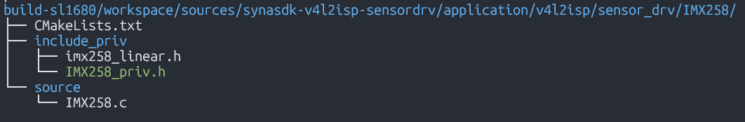
Step 1: Create a new directory for the sensor Create the new sensor directory with folder structure as shown below. Implementation follows the guideline provided by ISI documentation
Step 2: Add new sensor to list
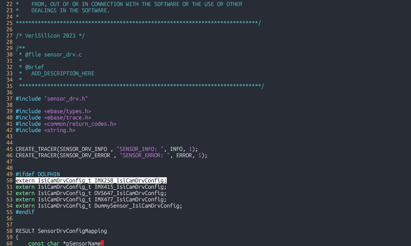
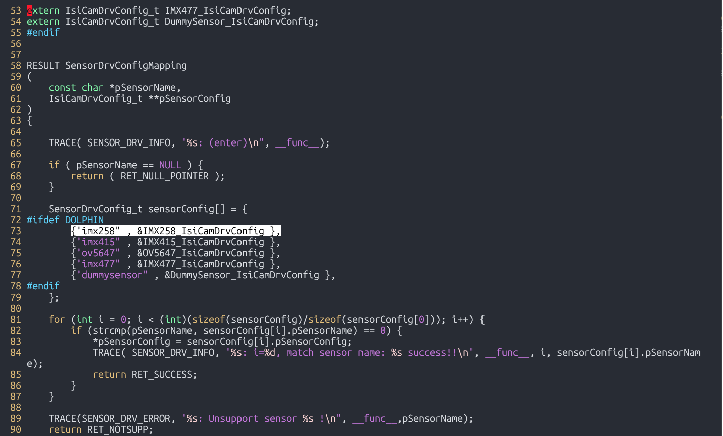
In build-sl1680/workspace/sources/synasdk-v4l2isp-sensordrv/application/v4l2isp/sensor_drv/sensor_drv.c, include the extern declaration for the new sensor and add the sensor to the driver list.
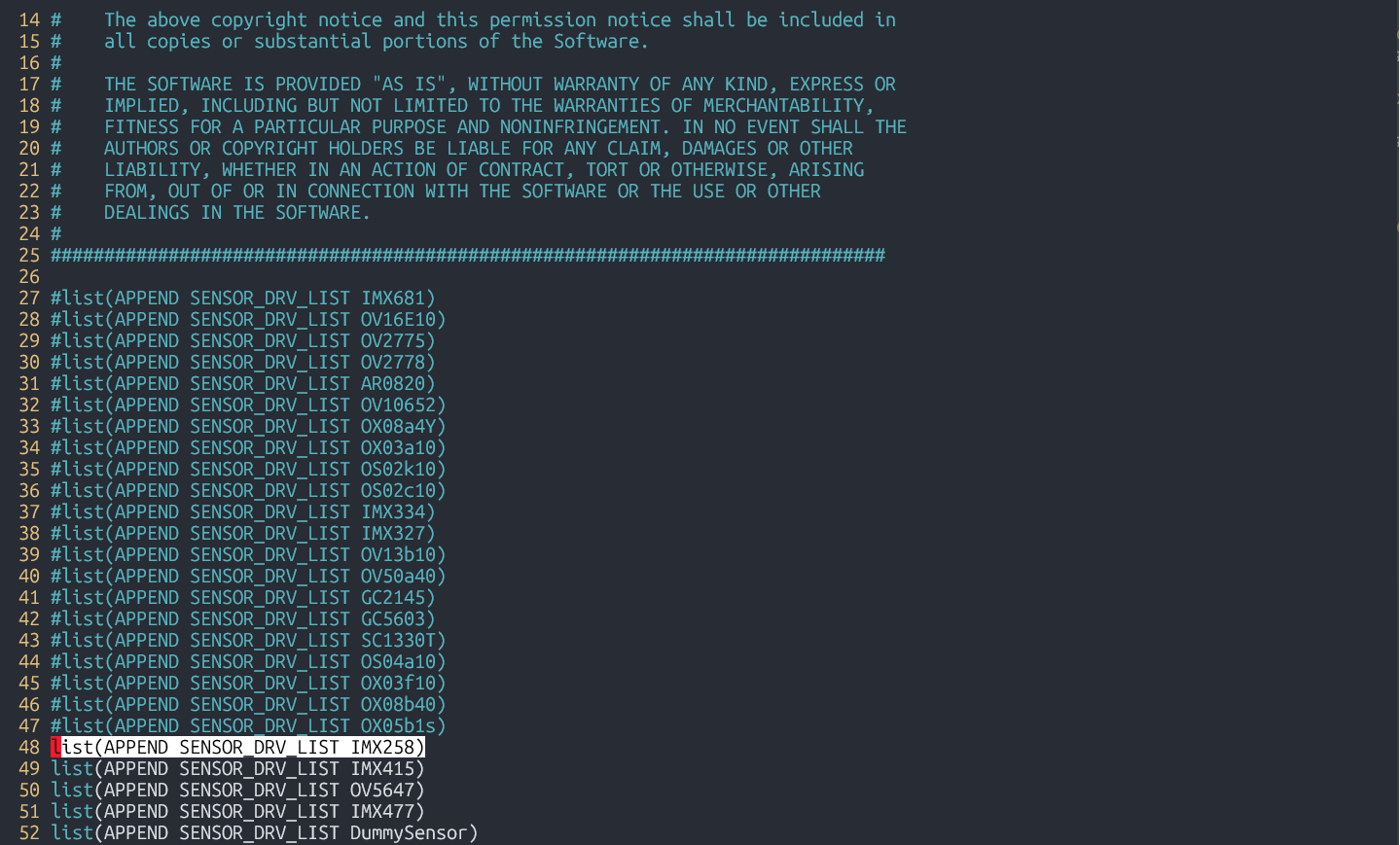
Step 3: Add new sensor to compilation
Append the new sensor to ‘SENSOR_DRV_LIST’ in build-sl1680/workspace/sources/synasdk-v4l2isp-sensordrv/application/v4l2isp/sensor_drv/sensor_drv_config.cmake
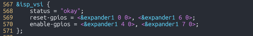
Step 4: Edit kernel DTS file
Edit build-sl1680/workspace/sources/linux-syna/arch/arm64/boot/dts/synaptics/dolphin-rdk.dts or sensor specific device tree overlay, to configure sensor related enable/reset GPIOs.
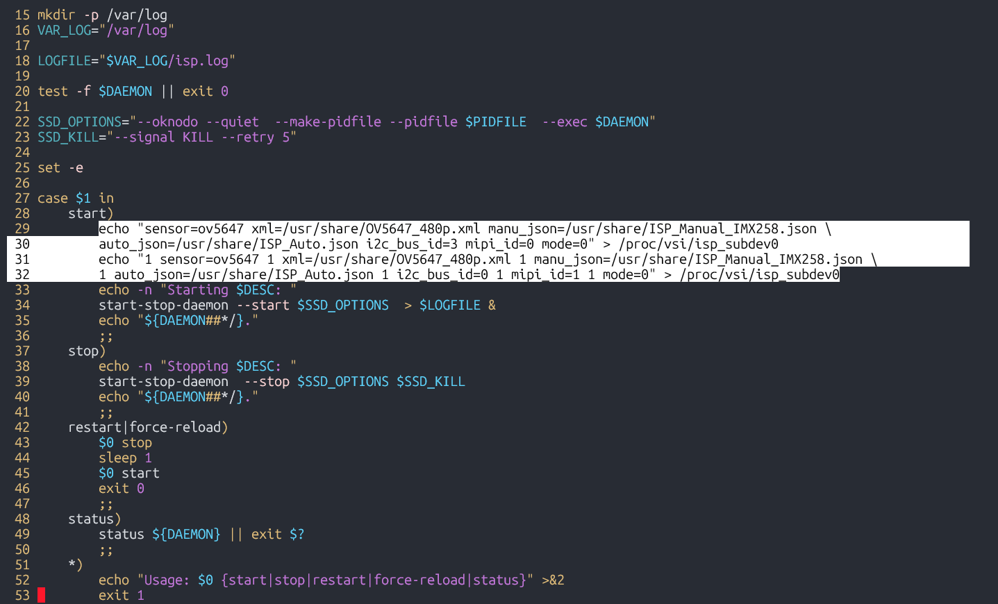
Step 5: Edit runtime configuration
Edit meta-synaptics/recipes-devtools/synasdk/files/isp_media_server.sh with sensor name, calibration and tuning JSON files, I2C Bus ID, MIPI index (0/1) and mode (resolution index) selecting required configuration from the list defined in the sensor driver file.
Step 6: Build new image containing these modifications
devtool build synasdk-v4l2isp-sensordrv
devtool build linux-syna
devtool build-image astra-media
Sensor Integration on SL2610
Any CSI-compatible sensor that already includes a V4L2 subdevice driver can be integrated directly. If a V4L2 subdevice driver is not available, you can refer to the ov5647.c implementation from the Linux mainline kernel as a guide to create one.
Make sure to enable the sensor driver as a module in the sl261x_defconfig
Device Tree Changes
sl2619-rdk.dts file should be changed to match the new sensor specific data. CSI is connected to I2C-0. Therefore, change the i2c0 device tree node, as explained below.
&i2c0 {
    cam_node: ov5647@36 {
        compatible = "ovti,ov5647";
        reg = <0x36>;
        status = "okay";

        pwdn-gpios = <&expander1 4 GPIO_ACTIVE_LOW>;
        clocks = <&osc>;

        port {
            cam_endpoint: endpoint {
                clock-lanes = <0>;
                data-lanes = <1 2>;
                clock-noncontinuous;
                remote-endpoint = <&csi_input>;
            };
        };
    };
};
Update the cam_node to use the new sensor’s compatible string and reg value (I2C slave address). Also adjust the clocks property to reflect the correct clock source for the sensor.
The port node defines the data path. The remote-endpoint specifies that sensor data enters the CSI driver through the csi_input port of the CSI node. This does not need to be modified.
However, properties such as clock-lanes, data-lanes, and clock-noncontinuous may need to be updated depending on the sensor, as these values vary between different devices.
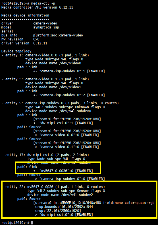
Expected Result
Correct sensor integration is confirmed if the media-ctl -p command shows an entry similar to this: