Astra Yocto Linux User Guide
Overview
This document describes the Synaptics Astra Linux OS environment and Board Support Package (BSP). It provides information on the components which make up the BSP and how to interface with them.
Supported Hardware
The following Reference Kits and platforms are covered by this guide:
Astra Machina (Foundation) SL1620
Astra Machina (Foundation) SL1640
Astra Machina (Foundation) SL1680
References
Introduction
The Synaptics Linux Board Support Package (BSP) contains the software and firmware required to operate Astra Machina. It contains the components needed to boot OSes and interface with the hardware. This guide provides a description of these software components and information on how to interface with them. This document is useful for users who want to evaluate Astra Machina and build products using these processors.
This document covers the components which are used by the Linux OS. For instructions on setting up the build environment and creating a Yocto-based image for Astra Machina, please see the Astra Yocto Linux Developer Guide.
Specific information about the Astra Machina hardware can be found on the Astra Machina Eval Platform page and source code repositories can be found on the Synaptics Astra GitHub page.
Interfacing with Astra Machina
Several methods exist for interfacing with Astra Machina, including using a graphical desktop on an external display. Additionally, Shell access is available through SSH, ADB, and the serial console.
The Graphical Desktop
Astra Machina’s graphical desktop is enabled by default. It can be displayed on an external display connected to the HDMI port or a MIPI display. Input can be provided by connecting a standard HID USB keyboard and mouse.
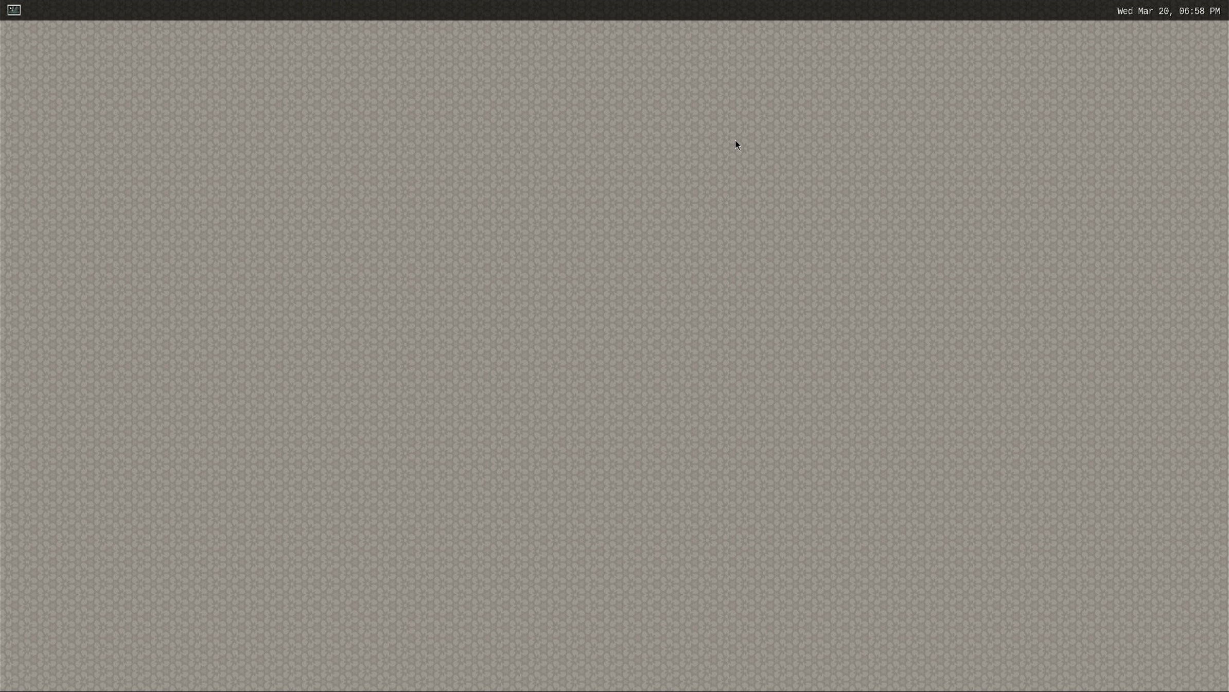
The Wayland Desktop on Astra Machina
Clicking on the icon in the top left corner will open a terminal.
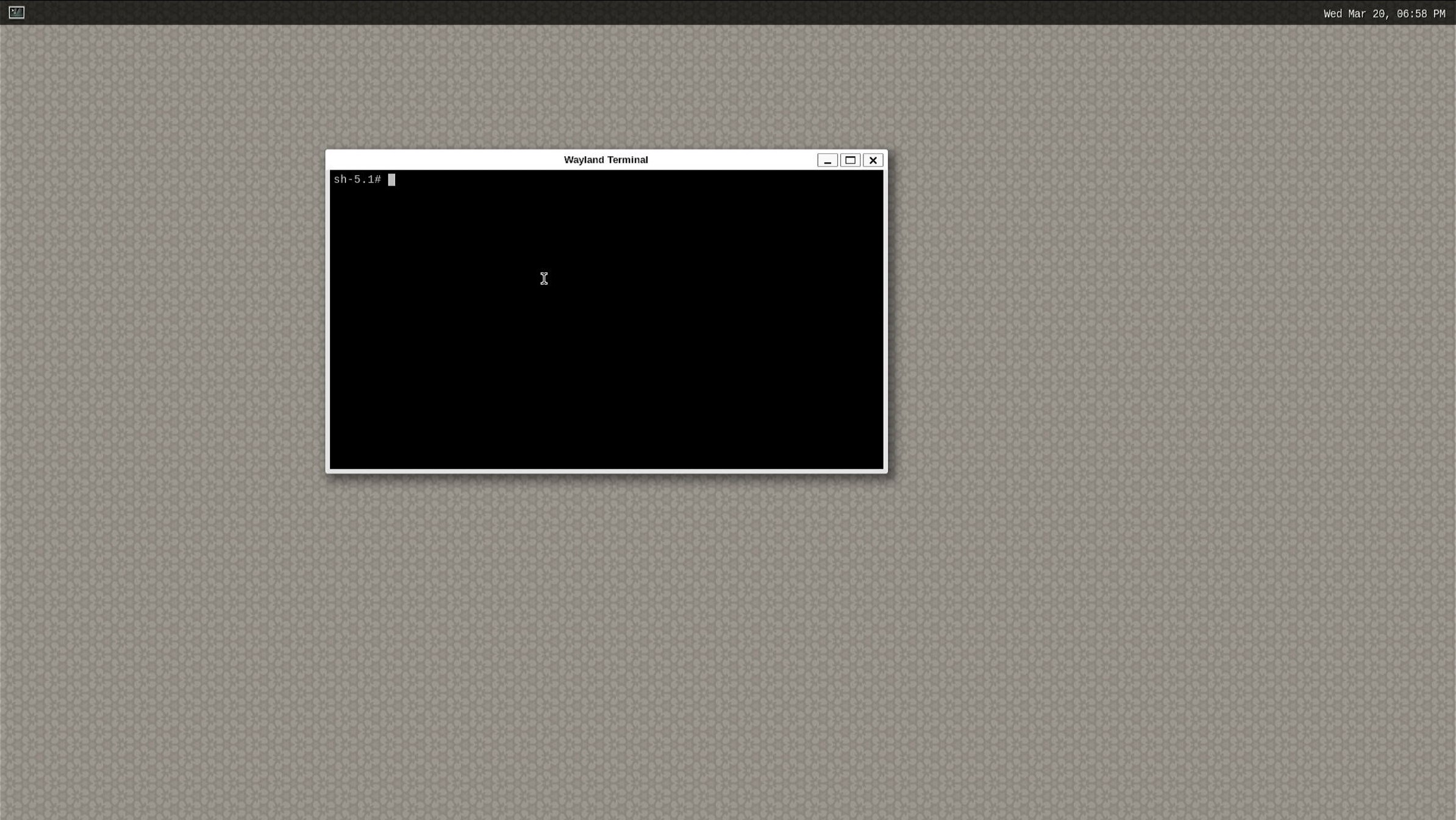
The Wayland Desktop with a terminal open
Note
HDMI is not currently supported on SL1620
The Shell with SSH
Astra Machina has ssh enabled by default. It will accept connections from ssh
clients over the network. Login with the username root. No password is required:
ssh root@10.10.10.100
Note
In the examples above the Astra Machina’s address is 10.10.10.100. Please replace this IP with the IP address of your device.
The Shell with ADB
Astra Machina supports Android Debug Bridge (ADB) over USB. ADB is used on Android devices and has been ported to Astra Machina. Google provides extensive documentation on ADB here.
To use ADB connect a USB cable from the host system to the USB Type-C USB 2.0 port on Astra Machina (next to the ethernet port).
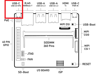
Astra Machina Component Diagram with USB Type-C USB 2.0 port highlighted
Google provides versions of ADB for Mac, Linux, and Windows. Once ADB is installed run adb devices to see all ADB devices
connected to the host. Then run:
adb shell
Or if there is more then one ADB device:
adb -s SL16x0 shell
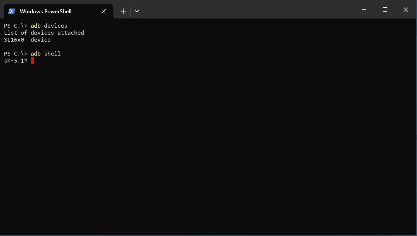
Using ADB with Windows Powershell
The Serial Console
Astra Machina provides a serial console which displays bootloader and OS messages to a terminal emulator running on the host system. These messages are useful for determining the status of Astra Machina early in the boot process or when a display is not connected. It can also provides useful information during operation. The serial console is also needed during the firmware update process.
Setting up the Serial Console
The serial console on Astra Machina can be accessed by connecting a USB-TTL adaptor to the RX, TX, and GND pins of the 40 pin GPIO connector. USB-TTL adaptors can either be a board with jumper wires or an integrated USB cable with separated pins.
USB TTL |
Astra Machina |
|---|---|
GND |
6 |
RXD |
8 |
TXD |
10 |
The following USB-TTL adaptors are officially approved to work with Astra Machina:
Adafruit USB to UART Debug / Console Cable (CP2102 Driver IC)
Pin Function
Color Code
Astra SL16x0 40-pin Connector
Astra SL16x0 40-pin Function
5V-Out
Red
NC
NC
TX-Out
Green
Pin-10
UART0_Rx-In
RX-In
White
Pin-8
UART0_Tx-Out
GND
Black
Pin-6
GND
CenryKay USB to UART Debug / Console Cable (CH340G Driver IC)
Pin Function
Color Code
Astra SL16x0 40-pin Connector
Astra SL16x0 40-pin Function
5V-Out
Red
NC
NC
TX-Out
Green
Pin-10
UART0_Rx-In
RX-In
White
Pin-8
UART0_Tx-Out
GND
Black
Pin-6
GND
Note
USB-TTL cables using PL2303 or FT232R driver ICs are not approved parts for use with Astra Machina.
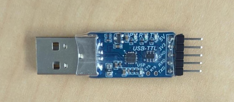
Example USB TTL board
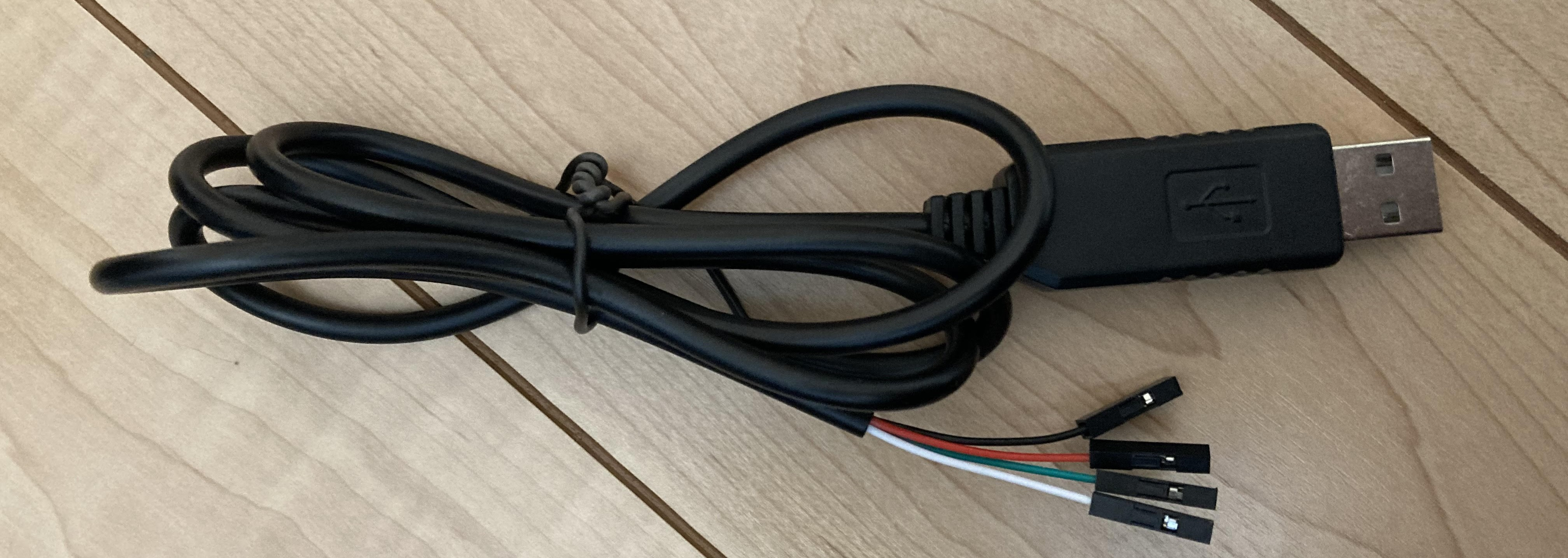
Example USB TTL cable
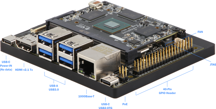
Astra Machina with 40 GPIO Header labeled
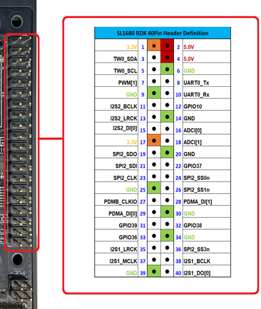
Astra Machina’s 40 Pin GPIO Header pinout
Some USB-TTL adaptors require installing a driver on Windows and Mac hosts. Please check with the adaptor’s manufacturer for instructions on downloading and installing the driver.
The serial console can be accessed using a terminal emulator program such as Putty, HyperTerminal, Tera Term, Screen, or Minicom.
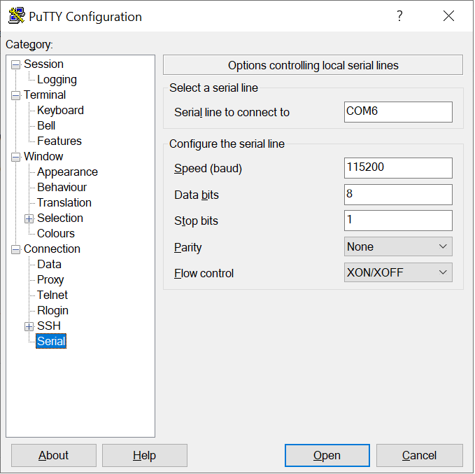
Putty terminal emulator on Windows
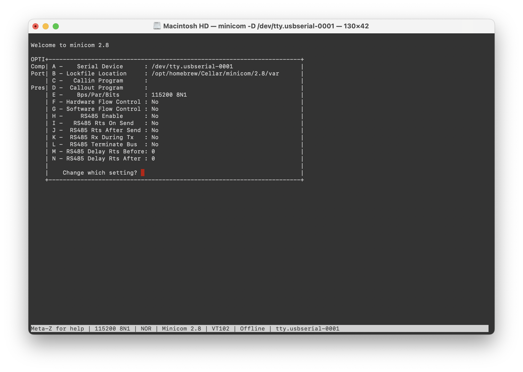
Minicon terminal emulator on Mac OS
Linux OS Login
After Linux successfully boots, a login prompt will be displayed in the
serial console. To login use the username root. No password is required.
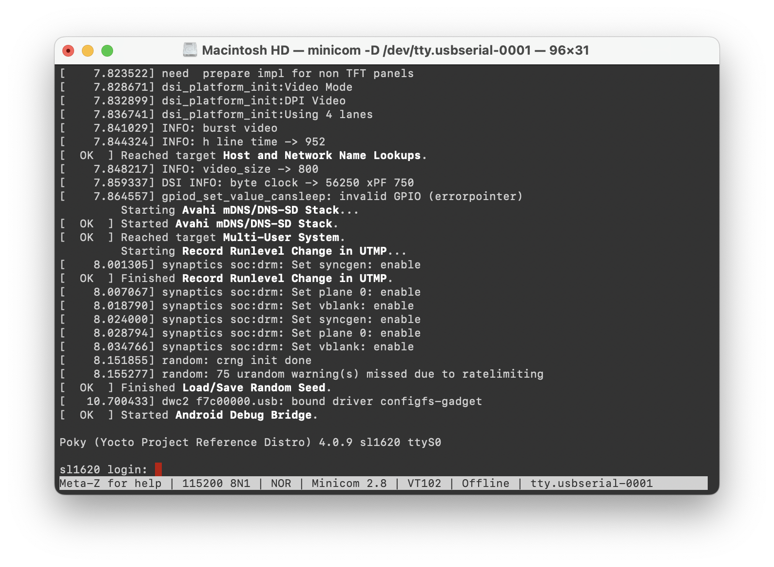
Successful boot seen in Minicom
Multimedia
The Astra Machina contains hardware and software components which accelerate the processing of multimedia workloads. The Linux BSP provides Gstreamer plugins which allow users to develop programs which utilize these multimedia components to improve multimedia performance. This section provides an overview on how to use the Gstreamer command line interface to build pipelines using these plugins. Information on the Gstreamer framework can be found at https://gstreamer.freedesktop.org/.
Gstreamer Plugins
Gstreamer uses plugin modules which are used to extend Gstreamer functionality. The Astra Machina uses plugins to allow its hardware components to be used in a Gstreamer pipeline. The tables below list plugins which are used by the codecs supported by the Astra Machina.
Video Codecs
SL1620
Codec |
Parser Plugin |
Decoder Plugin |
Encoder Plugin |
|---|---|---|---|
H.264 |
h264parse |
avdec_h264 |
N/A |
H.265 |
h265parse |
avdec_h265 |
N/A |
VP8 |
N/A |
avdec_vp8 |
N/A |
VP9 |
vp9parse |
avdec_vp9 |
N/A |
SL1640 / SL1680
Codec |
Parser Plugin |
Decoder Plugin |
Encoder Plugin |
|---|---|---|---|
H.264 |
h264parse |
v4l2h264dec |
v4l2h264enc |
H.265 |
h265parse |
v4l2h265dec |
N/A |
VP8 |
N/A |
v4l2vp8dec |
v4l2vp8enc |
VP9 |
vp9parse |
v4l2vp9dec |
N/A |
AV1 |
av1parse |
v4l2av1dec |
N/A |
Audio Codecs
Codec |
Parser Plugin |
Decoder Plugin |
Encoder Plugin |
|---|---|---|---|
AAC |
aacparse |
fdkaacdec |
fdkaacenc |
Vorbis |
N/A |
vorbisdec |
vorbisenc |
MPEG 2 |
mpegaudioparse |
avdec_mp2float |
avenc_mp2 |
MPEG 3 |
mpegaudioparse |
avdec_mp3 |
N/A |
AC3 |
N/A |
avdec_ac3 |
avenc_ac3 |
OPUS |
N/A |
avdec_opus |
avenc_opus |
Gstreamer Examples
To run the following Gstreamer examples, please make sure to set the following variables in your environment. These variables may need to be set when running commands from the serial console or a remote shell:
export XDG_RUNTIME_DIR=/var/run/user/0
export WAYLAND_DISPLAY=wayland-1
The XDG_RUNTIME_DIR variable specifies the directory which contains the
Wayland socket belonging to the user. The WAYLAND_DISPLAY variable
specifies which Wayland compositor to connect to.
The following examples use the gst-launch-1.0 command line program to construct a pipeline and begin playing it. The gst-launch-1.0 command takes in a list of element types separated by exclamation points. Elements can also contain optional properties. (see GStreamer documentation for more details). The examples below will show the structure of the command with a brief description. Followed by one or more examples.
Media Playback
Audio Sinks
The following examples use the ALSA audio sink to output audio using the ALSA audio API (for more details refer to the Gstreamer documentation for more details). The examples use the device hw:0,7 which corresponds to the HDMI output device on SL1680. Hardware devices can be found in the file /proc/asound/pcm. Below is an example of the pcm devices on SL1680. Device 0-7 corresponds to the HDMI device and will be used in the examples below.
Example /proc/asound/pcm output from SL1680:
root@sl1680:~# cat /proc/asound/pcm
00-00: soc-i2so1 snd-soc-dummy-dai-0 :  : playback 1
00-01: soc-i2so3 snd-soc-dummy-dai-1 :  : playback 1
00-02: soc-dmic snd-soc-dummy-dai-2 :  : capture 1
00-03: soc-i2si2 snd-soc-dummy-dai-3 :  : capture 1
00-04: btsco-in snd-soc-dummy-dai-4 :  : capture 1
00-05: soc-i2s-pri-lpbk snd-soc-dummy-dai-5 :  : capture 1
00-06: soc-i2s-hdmi-lpbk snd-soc-dummy-dai-6 :  : capture 1
00-07: soc-hdmio snd-soc-dummy-dai-7 :  : playback 1
Video Sinks
The following examples use the Wayland video sink to create a window and render the decoded frames (see GStreamer documentation for more details)
Audio Playback
Playing audio files involves reading and parsing the encoded audio data, decoding the data, and outputting it to the audio sink. Some data formats and audio sinks may also need to convert and resample the data before sending it to the audio sink:
gst-launch-1.0 filesrc location=audio_file ! parser ! decoder ! [ convert ] ! [ resample ] ! audiosink
This example plays an MP3 file using the speakers of the attached HDMI device:
gst-launch-1.0 filesrc location=audio_file.mp3 ! mpegaudioparse ! mpg123audiodec ! audioconvert ! audioresample ! alsasink device=hw:0,7
Video Playback
Playing a video file involves reading the file, demuxing a video stream, parsing the encoded data, and decoding the data using the video decoder. Finally, the decoded frames our output to the video sink:
gst-launch-1.0 filesrc location=video_file ! demux ! queue ! parser ! decoder ! videosink
The following example plays the main video stream of an MP4 file and displays the video using Wayland.
An example of a H265 encoded video file on SL1640 / SL1680:
gst-launch-1.0 filesrc location=test_file.mp4 ! qtdemux name=demux demux.video_0 ! queue ! h265parse ! v4l2h265dec ! waylandsink fullscreen=true
An example of a H265 encoded video file on SL1620:
gst-launch-1.0 filesrc location=test_file.mp4 ! qtdemux name=demux demux.video_0 ! queue ! h265parse ! avdec_h265 ! waylandsink fullscreen=true
A similar example, but with a file using AV1 encoding on SL1640 / SL1680:
gst-launch-1.0 filesrc location=test_file.mp4 ! qtdemux name=demux demux.video_0 ! queue ! av1parse ! v4l2av1dec ! waylandsink fullscreen=true
Audio / Video File Playback
Playing a file which contains both audio and video streams requires creating a pipeline which parses and decodes both streams:
gst-launch-1.0 filesrc location=video_file ! demux.video ! queue ! parser ! decoder ! videosink \
    demux.audio ! queue ! parser ! decoder ! [ convert ] ! [ resample ] ! audiosink
Play an MP4 file on SL1640 / SL1680 with a H265 encoded video stream and an AAC encoded audio stream:
gst-launch-1.0 filesrc location=test_file.mp4  ! qtdemux name=demux \
    demux.video_0 ! queue ! h265parse ! v4l2h265dec ! queue ! waylandsink fullscreen=true \
    demux.audio_0 ! queue ! aacparse ! fdkaacdec ! audioconvert ! alsasink device=hw:0,7
Recording
Audio Recording
Recording audio involves reading data from a capture device like a microphone, converting, encoding, and multiplexing the data before writing it to an output file:
gst-launch-1.0 -v alsasrc device=device ! queue ! convert ! encode ! mux ! filesink location=output file
The following example records audio from the ALSA capture device 0,2. It then converts the raw data into a format which can encoded into the Vorbis codec by the encoder. Once the data is encoded, it is then multiplexed into an Ogg container and written to the file /tmp/alsasrc.ogg:
gst-launch-1.0 -v alsasrc device=hw:0,2 ! queue ! audioconvert ! vorbisenc ! oggmux ! filesink location=/tmp/alsasrc.ogg
Camera
Astra Machina supports USB (UVC) and image sensor cameras using the V4L2 driver stack. This stack can be used with Gstreamer to construct pipelines using a camera.
Note
Image sensor cameras are only supported on SL1680 using SL1680’s ISP.
To display video captured from a camera to output it to the video sink:
gst-launch-1.0 v4l2src device=/dev/videoX ! "video data,framerate,format,width,height" ! video sink
The following example reads captured data from the V4L2 device /dev/video2 and applies the capabilities filter before sending the output to the wayland sink:
gst-launch-1.0 v4l2src device=/dev/video2 ! "video/x-raw,framerate=30/1,format=YUY2,width=640,height=480" ! waylandsink fullscreen=true
Gstreamer Playbin Plugin
Astra Machina contains the Gstreamer playbin plugin. This plugin can automatically determine what type of pipeline to construct based on automatic file type recognition (see Gstreamer documentation). This simplifies pipeline creation.
Playbin will autodetect the media file located at the specified uri, and create a pipeline for it. It will then display the video on the video sink and render the audio on the audio sink. The video-sink and audio-sink parameters are optional. If the parameters are not included, default video and audio sinks will be used instead:
gst-launch-1.0 playbin uri=file:///path/to/file video-sink="video sink" audio-sink="audio sink"
Using playbin the example in Audio Sinks can be reduced to:
gst-launch-1.0 playbin uri=file:///path/to/file video-sink="waylandsink fullscreen=true" audio-sink="alsasink device=hw:0,7"
GStreamer SyNAP Plugin
Astra Machina provides the Synaptics Gstreamer Plugins for AI (gstsynap) which allow adding ML processing to Gstreamer pipelines. These plugins use the SyNAP framework to interface with the hardware accelerators to improve the performance of ML processing. For information on SyNAP see Machine Learning with SyNAP below.
The Synaptics Gstreamer Plugins for AI consist of two plugins. The gstsynapinfer plugin, which uses SyNAP to handle AI inferencing and the gstsynapoverlay plugin which outputs the results from gstsynapinfer and overlays then on top of the source data.
The gstsynapinfer plugin can operate it two modes. The first mode outputs structured data which is then used by gstsynapoverlay. This supports common use cases such as drawing bounding boxes or overlaying text without having to write additional code. Here are several examples using gstsynapinfer to do the inferencing and gstsynapoverlay overlaying the results. These examples show inferencing running on a local file and an external USB camera.
Example of Object Detection with YOLOv8 (USB Camera Source):
gst-launch-1.0 v4l2src device=/dev/videoX ! video/x-raw,framerate=30/1,format=YUY2,width=640,height=480 ! videoconvert ! \
    tee name=t_data t_data. ! queue ! synapoverlay name=overlay label=/usr/share/synap/models/object_detection/coco/info.json \
    ! videoconvert ! waylandsink t_data. ! queue ! videoconvert ! videoscale ! video/x-raw,width=640,height=384,format=RGB  ! \
    synapinfer model=/usr/share/synap/models/object_detection/coco/model/yolov8s-640x384/model.synap mode=detector frameinterval=3 \
    ! overlay.inference_sink
Example of Object Detection with YOLOv8 (Video):
gst-launch-1.0 filesrc location=video_file.mp4 ! qtdemux name=demux demux.video_0 ! queue ! h264parse ! avdec_h264 ! videoconvert ! \
    tee name=t_data t_data. ! queue ! synapoverlay name=overlay label=/usr/share/synap/models/object_detection/coco/info.json ! \
    videoconvert ! waylandsink t_data. ! queue ! videoconvert ! videoscale ! video/x-raw,width=640,height=384,format=RGB  ! \
    synapinfer model=/usr/share/synap/models/object_detection/coco/model/yolov8s-640x384/model.synap mode=detector frameinterval=3 \
    ! overlay.inference_sink
Example of Face Detection with YOLOv5 (USB Camera Source):
gst-launch-1.0 v4l2src device=/dev/videoX ! video/x-raw,framerate=30/1,format=YUY2,width=640,height=480 ! videoconvert ! \
    tee name=t_data t_data. ! queue ! synapoverlay name=overlay ! videoconvert ! waylandsink t_data. ! queue ! videoconvert ! \
    videoscale ! video/x-raw,width=480,height=352,format=RGB  ! \
    synapinfer model=/usr/share/synap/models/object_detection/face/model/yolov5s_face_640x480_onnx_mq/model.synap mode=detector \
    frameinterval=3 ! overlay.inference_sink
Example of Pose Estimation with YOLOv8 (USB Camera Source):
gst-launch-1.0 v4l2src device=/dev/videoX ! video/x-raw,framerate=30/1,format=YUY2,width=640,height=480 ! videoconvert ! \
    tee name=t_data t_data. ! queue ! synapoverlay name=overlay ! videoconvert ! waylandsink t_data. ! queue ! videoconvert \
    ! videoscale ! video/x-raw,width=640,height=352,format=RGB  ! \
    synapinfer model=/usr/share/synap/models/object_detection/body_pose/model/yolov8s-pose/model.synap mode=detector frameinterval=3 \
    ! overlay.inference_sink
Example of Pose Estimation with YOLOv8 (Video):
gst-launch-1.0 filesrc location=fitness.mp4 ! qtdemux name=demux demux.video_0 ! queue ! h264parse ! avdec_h264 ! videoconvert ! \
    tee name=t_data t_data. ! queue ! synapoverlay name=overlay ! videoconvert ! waylandsink t_data. ! queue ! videoconvert ! \
    videoscale ! video/x-raw,width=640,height=352,format=RGB  ! \
    synapinfer model=/usr/share/synap/models/object_detection/body_pose/model/yolov8s-pose/model.synap mode=detector frameinterval=3 \
    ! overlay.inference_sink
Note
Replace /dev/videoX with the device file associated with your external USB camera.
In gstsynapinfer’s second mode, inference results are output as a JSON string. This allows an application to handle the overlay directly or do additional processing on the results.
We provide a sample application which makes use of gstsynapinfer’s second mode. The app plays a video while simultaneously performing image classification on the video frames, and then overlaying labels of the results onto the video. A prebuilt version of the application is included in the Astra system image.
Run the example application using the following command:
gst-ai --appmode=IC --input=test_file.mp4 --output=screen --paramfile=/usr/share/gst-ai/ic.json
The gst-ai program uses a JSON parameter file to set additional configuration options. These options include decode mode, model, model meta-data,
count, confidence threshold, and post processing mode. The Astra Machina image provides a default JSON file for image classification at
/usr/share/gst-ai/ic.json. The supported decode modes (decmode) are ffmpeg and v4l2. When set to ffmpeg the gst-ai program will use the
ffmpeg library to perform decoding of the video stream in software. When v4l2 is set then gst-ai will use the V4L2 APIs
to perform decoding of the video stream using hardware acceleration.
Note
SL1620 requires decmode to be set to ffmpeg since it does not support V4L2 decoding.
Multimedia Demo Applications
We also provide two demo QT applications which demonstate the Multimedia and AI capabilities of Astra Machina. The Syna Video Player app demonstates decoding and playing up to four video streams. The Syna AI Player app demonstrates the AI capabilities of Astra Machina by performing object detection, face detection, and pose estimation examples.
The apps require the following environment variable to be set:
export XDG_RUNTIME_DIR=/var/run/user/0
export WESTON_DISABLE_GBM_MODIFIERS=true
export WAYLAND_DISPLAY=wayland-1
export QT_QPA_PLATFORM=wayland
Multimedia Demo Customization
Both applications use QML files for their configuration. This allows users to customize the applications. Customizations include modifying what videos are used in the application. Since no sample video files are preinstalled on the Astra Machina image, users will need to add their own video files to the application’s QML files. The default QML files are preinstalled in /home/root/demos/qmls.
Syna Video Player
The Syna Video Player application demonstrates Astra Machina’s ability to play and decode videos. It supports playing a single video, or playing up to four videos in a grid.
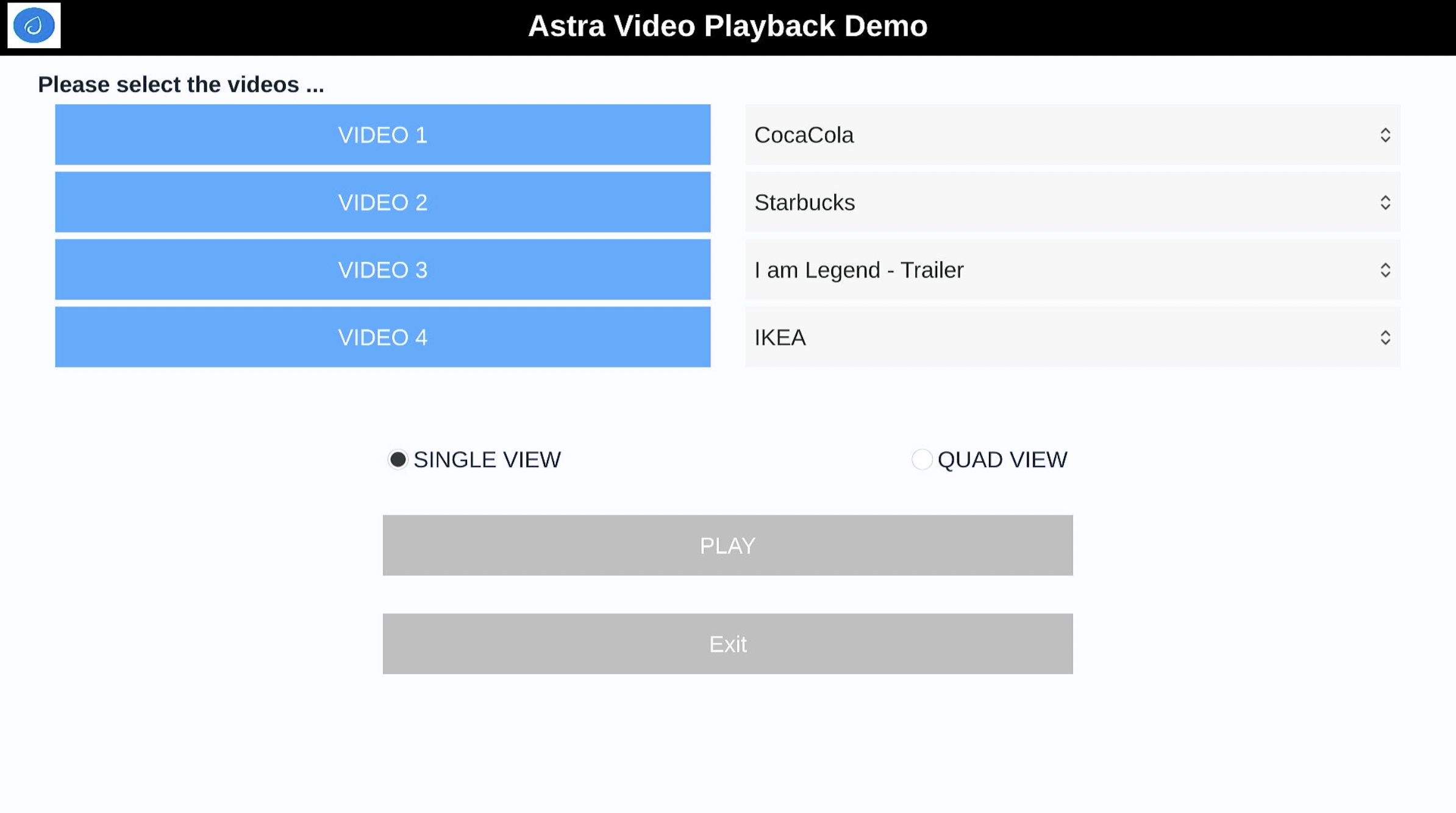
The main screen of Syna Video Player
Run the Syna Video Player:
root@sl1680:~# syna-video-player --mach=sl1680 --mode=ffmpeg
The Syna Video Player expects two paramaters, the machine type and the mode. The machine type is the version of Astra Machina which the application is running on.
The valid options are sl1620, sl1640 and sl1680. The mode specifies which mode of decoding should be used. The options are ffmpeg and v4l2.
When set to ffmpeg the Syna Video Player application will use the ffmpeg library to perform decoding of the video stream in software.
When v4l2 is set then Syna Video Player will use the V4L2 APIs to perform decoding of the video stream using hardware acceleration.
Note
SL1620 requires mode to be set to ffmpeg since it does not support V4L2 decoding.
The information on the video files is defined in the QML files in /home/root/demos/qmls/. Please update the video names and path in these files so that Syna Video Player
can locate the videos installed on your system. The video information is set in the file <mach>-<mode>.qml. For example, to update the video files on SL1680 in ffmpeg mode,
modify /home/root/demos/qmls/sl1680-ffmpeg.qml.
Syna AI Player
The Syna AI Player application uses the above gstreamer pipelines to show object detection, face detection, and pose estimation. It also supports Multi AI view which does object detection, face detection, and pose estimation simultaniously while playing a video.
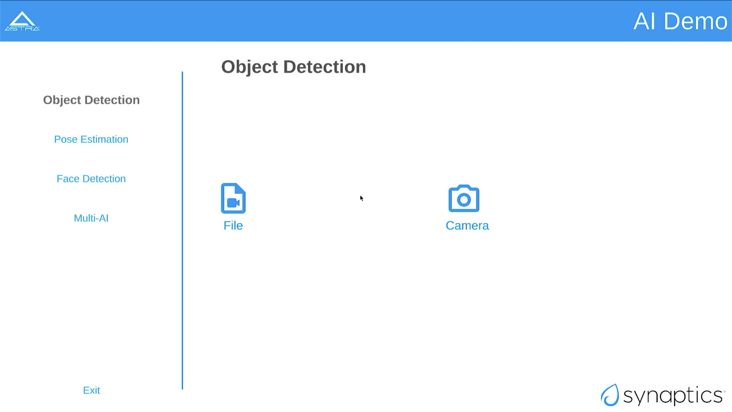
The main screen of Syna AI Player
Run the Syna AI Player:
root@sl1680:~# syna-ai-player --mach=sl1680
The Syna AI Player expects the machine type parameter. The machine type is the version of Astra Machina which the app is running on.
The valid options are sl1620, sl1640 and sl1680.
The information on the video file used in the Multi View window is defined in the QML files in /home/root/demos/qmls/. Please update the video name and path in this file so that Syna AI Player
can locate the video installed on your system. The video information is set in the file /home/root/demos/qmls/panels/MultiAi.qml.
Note
Multi AI mode requires 3 seperate cameras. One of which needs to be a USB 3.0 device.
Machine Learning with SyNAP
Astra Machina uses the SyNAP framework for execution of neural networks using the platform’s hardware accelerators. This framework allows users to run programs which take advantage of the Neural Processing Unit (NPU) and Graphics Processing Unit (GPU) to accelerate the execution of neural networks. (see the SyNAP documentation for more details.)
Connectivity
Bluetooth and Wi-Fi are supported on Astra Machina through on-board chip solutions and external hardware. The following table lists the various on-board chips and external solutions:
SL Processor |
Wireless Device |
Physical Interface (M.2 PCIe / M.2 SDIO) |
Software Information |
|---|---|---|---|
SL1620 |
SYNA 43711 |
M.2 SDIO |
|
SL1640 |
SYNA 43752 |
M.2 PCIe |
|
SL1680 |
SYNA 43752 |
M.2 PCIe |
|
The Synaptics Astra Linux BSP contains all of the drivers and firmware required to use the 43xxx modules with both PCIe and SDIO interfaces. Wireless network management is handled by the WPA Supplicant daemon which key negotiation with a WPA Authenticator. It supports WEP, WPA, WPA2, and WPA3 authentication standards. ( See wpa_supplicant for more details)
Setting up Wifi with WPA Supplicant
The following section describes how to setup Wifi on Astra Machina using WPA Supplicant.
Bringing up the WLAN Interface
Use ifconfig to instruct the kernel to bring up the wlan interface:
ifconfig wlan0 up
Creating the WPA Supplicant Configuration File
WPA Supplicant uses a config file to configure the Wifi connection. This configuration file is located in /etc/wpa_supplicant.
Create the /etc/wpa_supplicant directory:
mkdir -p /etc/wpa_supplicant
Create the file /etc/wpa_supplicant/wpa_supplicant-wlan0.conf with options for your Wifi Network.
Contents of an example wpa_supplicant-wlan0.conf:
ctrl_interface=/var/run/wpa_supplicant
ctrl_interface_group=0
update_config=1

network={
    ssid="network_name"
    psk=5ba83b0673ea069dafe5d5f1af8216771c13be6ad6f11dac9dc0e90b0c604981
    key_mgmt=WPA-PSK
    scan_ssid=1
}
Configure systemd-networkd
The wlan interface needs to be enabled in the systemd-networkd system daemon configuration.
Create the new file /etc/systemd/network/25-wlan.network with the following contents:
[Match]
Name=wlan0

[Network]
DHCP=ipv4
Enable Wifi Services
The network daemons need to be restarted to load the new configuration.
Restart network daemons:
systemctl restart systemd-networkd.service
systemctl restart wpa_supplicant@wlan0.service
Enable wpa_supplicant on boot up:
systemctl enable wpa_supplicant@wlan0.service
Performing throughput tests
The following section describes how to run throughput tests using iPerf commands in TCP and UDP modes.
TCP traffic
Client Side:
$ iperf -c <IP address of iperf server> -i 1 -w 12M -t 60 -l 1470
Server side:
$ iperf -s -i 1 -w 12M -l 1470
UDP traffic
Client side:
$ iperf -c <IP address of iperf server> -i 1 -w 12M -u -b 1000M -t 60 -l 1470
Server side:
$ iperf -s -i 1 -w 12M -l 1470
Using the Bluetooth A2DP source role
Searching and connecting to the headset
First you need to enter the Bluetooth console using the following command:
root@sl1640:~# bluetoothctl
[bluetooth]#
Once in the Bluetooth console you can run various commands to control the Bluetooth stack described in the following paragraphs.
You can show information about the Bluetooth controller on the board with the show command:
[bluetooth]# show
Controller C0:F5:35:AA:7D:8F (public)
        Name: sl1640
        Alias: sl1640
        Class: 0x00000000
        Powered: no
        Discoverable: no
        DiscoverableTimeout: 0x000000b4
        Pairable: yes
        UUID: Audio Source              (0000110a-0000-1000-8000-00805f9b34fb)
        UUID: Generic Attribute Profile (00001801-0000-1000-8000-00805f9b34fb)
        UUID: Generic Access Profile    (00001800-0000-1000-8000-00805f9b34fb)
        UUID: PnP Information           (00001200-0000-1000-8000-00805f9b34fb)
        UUID: A/V Remote Control Target (0000110c-0000-1000-8000-00805f9b34fb)
        UUID: A/V Remote Control        (0000110e-0000-1000-8000-00805f9b34fb)
        UUID: Device Information        (0000180a-0000-1000-8000-00805f9b34fb)
        Modalias: usb:v1D6Bp0246d0541
        Discovering: no
        Roles: central
        Roles: peripheral
Advertising Features:
        ActiveInstances: 0x00 (0)
        SupportedInstances: 0x06 (6)
        SupportedIncludes: tx-power
        SupportedIncludes: appearance
        SupportedIncludes: local-name
        SupportedSecondaryChannels: 1M
        SupportedSecondaryChannels: 2M
        SupportedSecondaryChannels: Coded
In order to connect to the headset you first need to power on the bluetooth controller:
[bluetooth]# power on
[CHG] Controller C0:F5:35:AA:7D:8F Class: 0x00080000
Changing power on succeeded
[CHG] Controller C0:F5:35:AA:7D:8F Powered: yes
You then need to set the controller in pairable mode:
[bluetooth]# pairable on
Changing pairable on succeeded
You can then search for the headset (make sure the headset is in discoverable mode):
[bluetooth]# scan on
Discovery started
[CHG] Controller C0:F5:35:AA:7D:8F Discovering: yes
[NEW] Device 2D:9A:A9:4F:54:37 2D-9A-A9-4F-54-37
[NEW] Device 4E:E7:B0:20:2A:11 4E-E7-B0-20-2A-11
[NEW] Device 7F:84:A3:29:E9:E9 7F-84-A3-29-E9-E9
[NEW] Device 6A:B0:95:7E:58:79 6A-B0-95-7E-58-79
[NEW] Device 7E:4D:8F:C4:3B:6F 7E-4D-8F-C4-3B-6F
[NEW] Device 40:93:CE:4D:F1:8E 40-93-CE-4D-F1-8E
[NEW] Device 47:14:71:A3:79:A9 47-14-71-A3-79-A9
[NEW] Device 67:62:9C:4B:F9:7D 67-62-9C-4B-F9-7D
[NEW] Device 8C:F8:C5:BD:6F:1D DTKBTQ3
[NEW] Device 0A:73:76:09:55:C0 BT208
This command returns the MAC address of all the devices that are currently discoverable. You need to identify the one of the headset you want to pair.
Once you found the headset you can pair to it by using the pair command with the MAC address of the headset:
[bluetooth]# pair 0A:73:76:09:55:C0
Attempting to pair with 0A:73:76:09:55:C0
[CHG] Device 0A:73:76:09:55:C0 Connected: yes
[CHG] Device 0A:73:76:09:55:C0 Bonded: yes
[CHG] Device 0A:73:76:09:55:C0 UUIDs: 00001108-0000-1000-8000-00805f9b34fb
[CHG] Device 0A:73:76:09:55:C0 UUIDs: 0000110b-0000-1000-8000-00805f9b34fb
[CHG] Device 0A:73:76:09:55:C0 UUIDs: 0000110c-0000-1000-8000-00805f9b34fb
[CHG] Device 0A:73:76:09:55:C0 UUIDs: 0000110e-0000-1000-8000-00805f9b34fb
[CHG] Device 0A:73:76:09:55:C0 UUIDs: 0000111e-0000-1000-8000-00805f9b34fb
[CHG] Device 0A:73:76:09:55:C0 ServicesResolved: yes
[CHG] Device 0A:73:76:09:55:C0 Paired: yes
Pairing successful
[CHG] Device 0A:73:76:09:55:C0 ServicesResolved: no
[CHG] Device 0A:73:76:09:55:C0 Connected: no
The next step is to mark the device as trusted:
[bluetooth]# trust 0A:73:76:09:55:C0
[CHG] Device 0A:73:76:09:55:C0 Trusted: yes
Changing 0A:73:76:09:55:C0 trust succeeded
The last step is to setup the connection with the headset:
[bluetooth]# connect 0A:73:76:09:55:C0
Attempting to connect to 0A:73:76:09:55:C0
[CHG] Device 0A:73:76:09:55:C0 Connected: yes
[NEW] Endpoint /org/bluez/hci0/dev_0A_73_76_09_55_C0/sep1
[NEW] Transport /org/bluez/hci0/dev_0A_73_76_09_55_C0/sep1/fd0
Connection successful
[BT208]# [  286.922414] input: BT208 (AVRCP) as /devices/virtual/input/input1
[CHG] Transport /org/bluez/hci0/dev_0A_73_76_09_55_C0/sep1/fd0 Volume: 0x0060 (96)
[DEL] Device D4:D2:D6:4F:80:60 445HD_BT_60
[CHG] Device 0A:73:76:09:55:C0 ServicesResolved: ye
[BT208]#
If the connection was successful the console prompt will show the name of device we connected to.
We can now get the information about the device:
[BT208]# info
Device 0A:73:76:09:55:C0 (public)
        Name: BT208
        Alias: BT208
        Class: 0x00240404
        Icon: audio-headset
        Paired: yes
        Bonded: yes
        Trusted: yes
        Blocked: no
        Connected: yes
        LegacyPairing: no
        UUID: Headset                   (00001108-0000-1000-8000-00805f9b34fb)
        UUID: Audio Sink                (0000110b-0000-1000-8000-00805f9b34fb)
        UUID: A/V Remote Control Target (0000110c-0000-1000-8000-00805f9b34fb)
        UUID: A/V Remote Control        (0000110e-0000-1000-8000-00805f9b34fb)
        UUID: Handsfree                 (0000111e-0000-1000-8000-00805f9b34fb)
        RSSI: -69
        TxPower: 4
Playing music to the headset
In order to test playback you need to upload a sound file (in .wav format) to the board for instance using scp.
The file can be played to the A2DP sink using the aplay command. The command takes as parameter the MAC address of the
headeset (in the example below 0A:73:76:09:55:C0) and the name of wave file (in the example below
/home/root/example.wav):
root@sl1640:~# aplay --verbose -D  bluealsa:DEV=0A:73:76:09:55:C0 -t wav /home/root/example.wav
Playing WAVE '/home/root/example.wav' : Signed 16 bit Little Endian, Rate 48000 Hz, Stereo
Plug PCM: BlueALSA PCM: /org/bluealsa/hci0/dev_0A_73_76_09_55_C0/a2dpsrc/sink
BlueALSA BlueZ device: /org/bluez/hci0/dev_0A_73_76_09_55_C0
BlueALSA Bluetooth codec: SBC
Its setup is:
  stream       : PLAYBACK
  access       : RW_INTERLEAVED
  format       : S16_LE
  subformat    : STD
  channels     : 2
  rate         : 48000
  exact rate   : 48000 (48000/1)
  msbits       : 16
  buffer_size  : 24000
  period_size  : 6000
  period_time  : 125000
  tstamp_mode  : NONE
  tstamp_type  : GETTIMEOFDAY
  period_step  : 1
  avail_min    : 6000
  period_event : 0
  start_threshold  : 24000
  stop_threshold   : 24000
  silence_threshold: 0
  silence_size : 0
  boundary     : 6755399441055744000
The Linux Boot Process
Before the Linux Kernel begins executing on Astra Machina, low level firmware and software initializes the hardware and prepares the system for boot. This section provides an overview of the software components which prepare the system for booting the Linux Kernel.
Software Overview
Astra Machina uses a multistage boot process. This section gives a brief description of each component.
Preboot Firmware
The Preboot firmware is a collection of low level firmware which initializes specific hardware components and loads the software which runs in the Arm TrustZone environment. Once the Preboot firmware completes, execution will be transferred to the bootloader. The Preboot firmware is provided as binary images which are written to the boot device.
Bootloader
Astra Machina uses the Synaptics U-Boot (SUBoot) bootloader to do additional hardware initialization and to boot the Linux Kernel. SUBoot is based on the open source U-Boot project. (U-Boot Documentation)
Linux Kernel and Device Tree
Astra Machina primarily run OSes which use the Linux Kernel. The Linux Kernel provides the environment in which applications run and it manages resources such as CPU, memory, and devices. Generally, the Linux Kernel will be built as part of the Yocto build process described in the Astra Yocto User Guide.
The Linux Kernel uses Device Tree data structures to describe the
hardware components and their configurations on the system. The device
tree source files are in the Linux Kernel source tree under that path
arch/arm64/boot/dts/synaptics/. These files are maintained in the Astra Linux Kernel Overlay repository.
Root File System
The root file system (rootfs) contains all the user space binaries and libraries needed to execute programs in the Linux OS along with system configuration files. The prebuilt images use Yocto to build the rootfs. Instructions on how to build and configure a rootfs using Yocto can be found in the Astra Yocto Linux Developer Guide.
U-Boot
As mentioned above, Astra Machina uses U-Boot as its bootloader. There are three types of U-Boot which are used with Astra Machina. In addition to SUBoot, there are SPI U-Boot and USB U-Boot variants which are used to flash or recover a device.
image type |
image usage |
|---|---|
SPI U-Boot |
burn eMMC image via TFTP server or USB drive |
USB U-Boot |
burn eMMC image via TFTP server of USB host |
SUBoot |
burn eMMC image via TFTP server or USB drive, Booting Linux |
USB U-Boot and SPI U-Boot are used to boot a device which does not have an image written to the eMMC or to do a update which overwrites all of the contents of the eMMC.
USB U-Boot allows the board to receive a copy of the USB version of U-Boot over the USB interface. The host system runs the usb_boot tool to transfer the USB U-Boot image to the board and execute it. Once USB U-Boot is running on the board it can be used to write an image to the eMMC.
SPI U-Boot is similar to USB U-Boot except that U-Boot runs from SPI flash. The SPI flash may be located on the main board of Astra Machina or it may be a located on a SPI daughter card which is plugged into the device. Once SPI U-Boot is running on the board it can be used to write an image to the eMMC.
Booting from SPI and SD Cards
Astra Machina’s I/O board has a jumper labeled SD-Boot. This jumper controls
whether the device boots from the eMMC or the internal SPI flash. If the jumper
is attached then the device will boot from the internal SPI flash. Remove the jumper
to boot from eMMC.

Astra Machina Component Diagram with SD-Boot jumper highlighted
Astra Machina’s internal SPI flash comes preprogrammed with SPI U-Boot. When the SD-Boot jumper is connected the device will boot from the SD card inserted in the SD card slot. If no SD card is inserted the SPI U-Boot will boot to the U-Boot prompt “=>”. The U-Boot prompt can be used to set variables, or flash the eMMC and internal SPI flash.
Note
Booting from SD cards is not supported on SL1620
Generating Bootable SD Card Images
Creating a bootable SD card requires converting an existing image into a format suitable for writing
to the SD card. You can convert either prebuilt release images or an image you built yourself.
Run the gen_sd.sh script from within the image directory. You can find the gen_sd.sh script
on GitHub.
Click the “Download Raw File” to download the script. The script runs in a Linux environment with the
mkfs.ext4, gzip, gdisk, and sgdisk utilties installed.
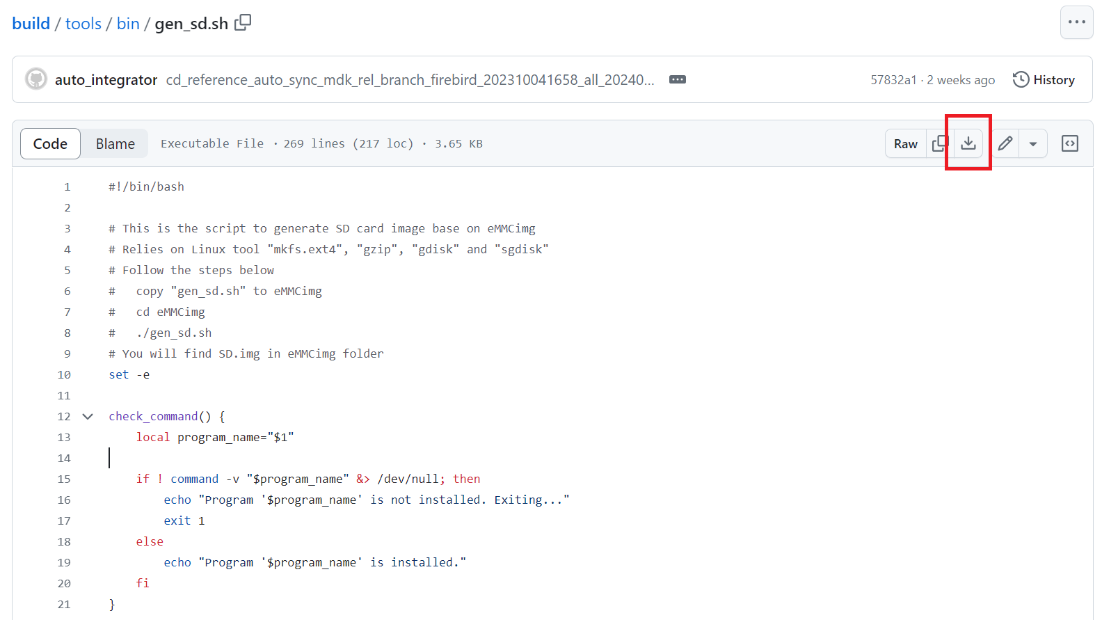
Downloading gen_sd.sh from GitHub
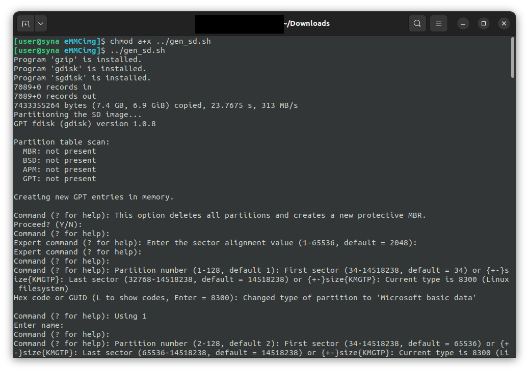
Running gen_sd.sh from within the prebuilt V1.0.0 eMMCimg directory
During the conversion gen_sd.sh will create the new file SD.img. This is the new image file which
will be written to the SD card.
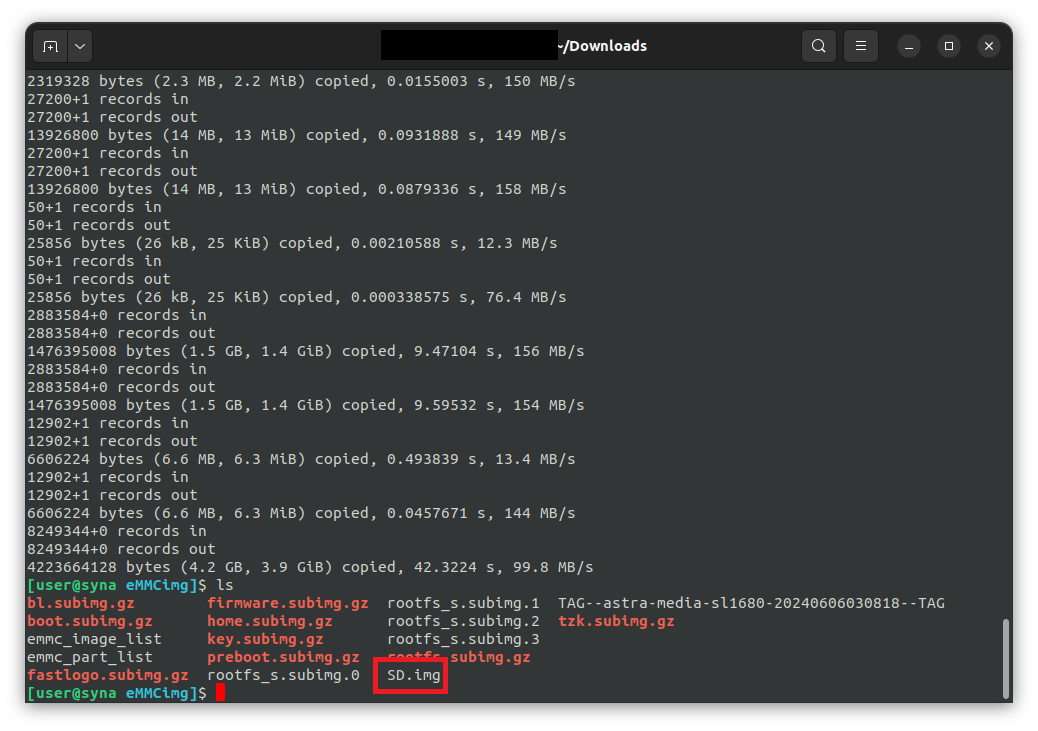
After gen_sd.sh completed
Writing Bootable Images to the SD Card
The SD.img file is written to the SD card using the Balena Etcher tool.
Begin by downloading and installing the tool. Then run the tool and follow the steps in the UI to select the image and target device.
Finally, click the flash button to begin the process.
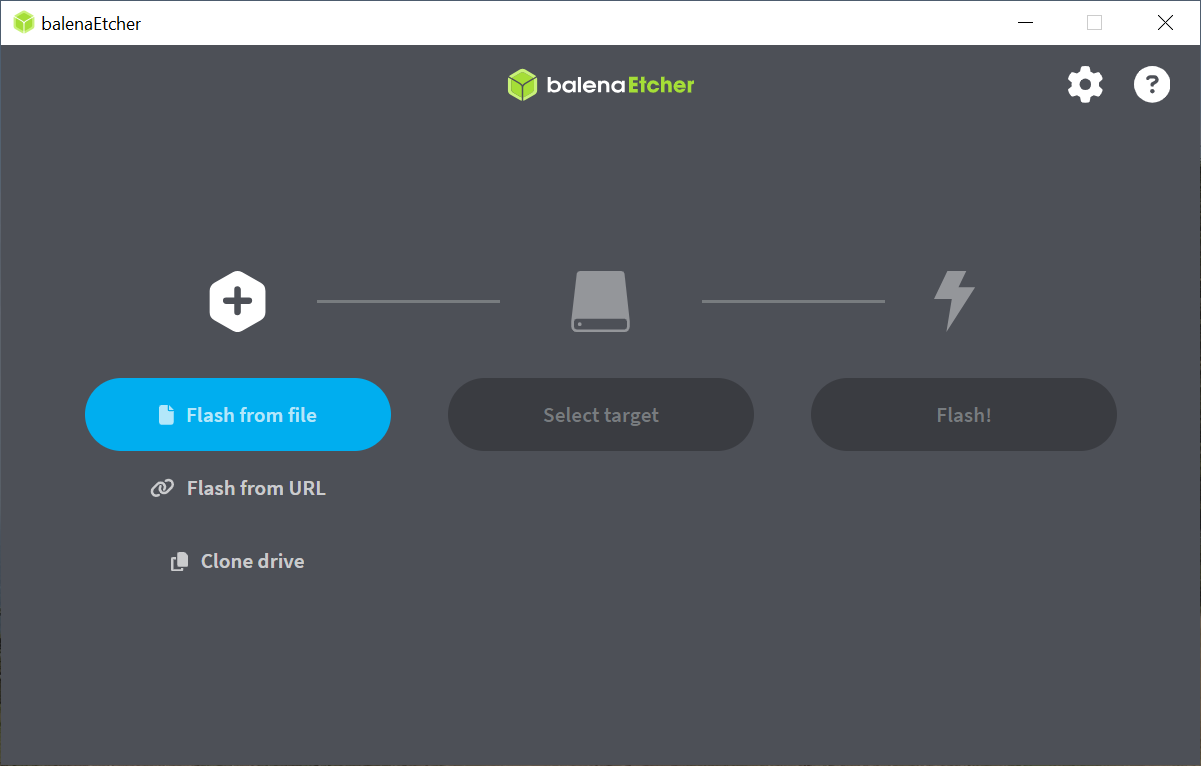
The start screen of Balena Etcher
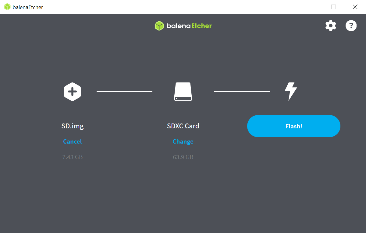
Balena Etcher after selecting the image file and target device
After the flashing process completes, the SD card will now be ready to boot Astra Machina.
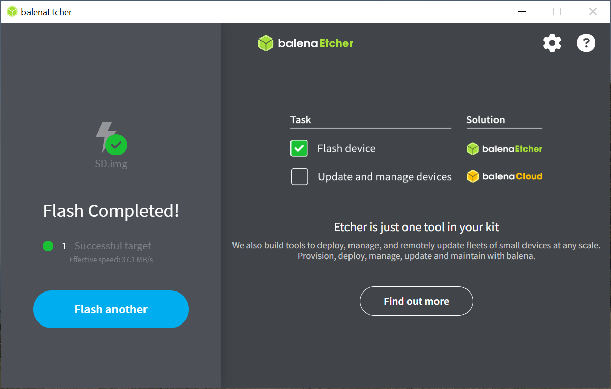
Balena Etcher after successfully flashinge image to the SD card
U-Boot Prompt with SUBoot
When booting from the internal eMMC or from an SD card, SUBoot will automatically load the Linux kernel. However, this process can be interrupted by pressing any key in the serial console during the boot process. If U-Boot detects a keypress then it will stop at the U-Boot prompt “=>”. The U-Boot prompt can be used to set variables, or flash the eMMC and internal SPI flash. By default the timeout in which U-Boot will wait for input is set to 0, so key presses need to be sent before U-Boot starts.
Updating the Firmware
On power on, Astra Machina will read the firmware, bootloader, and the Linux Kernel from a boot device. The most common boot device is an eMMC device on the board. This section will discuss how to write a boot image to the eMMC and internal SPI flash.
The Astra System Image
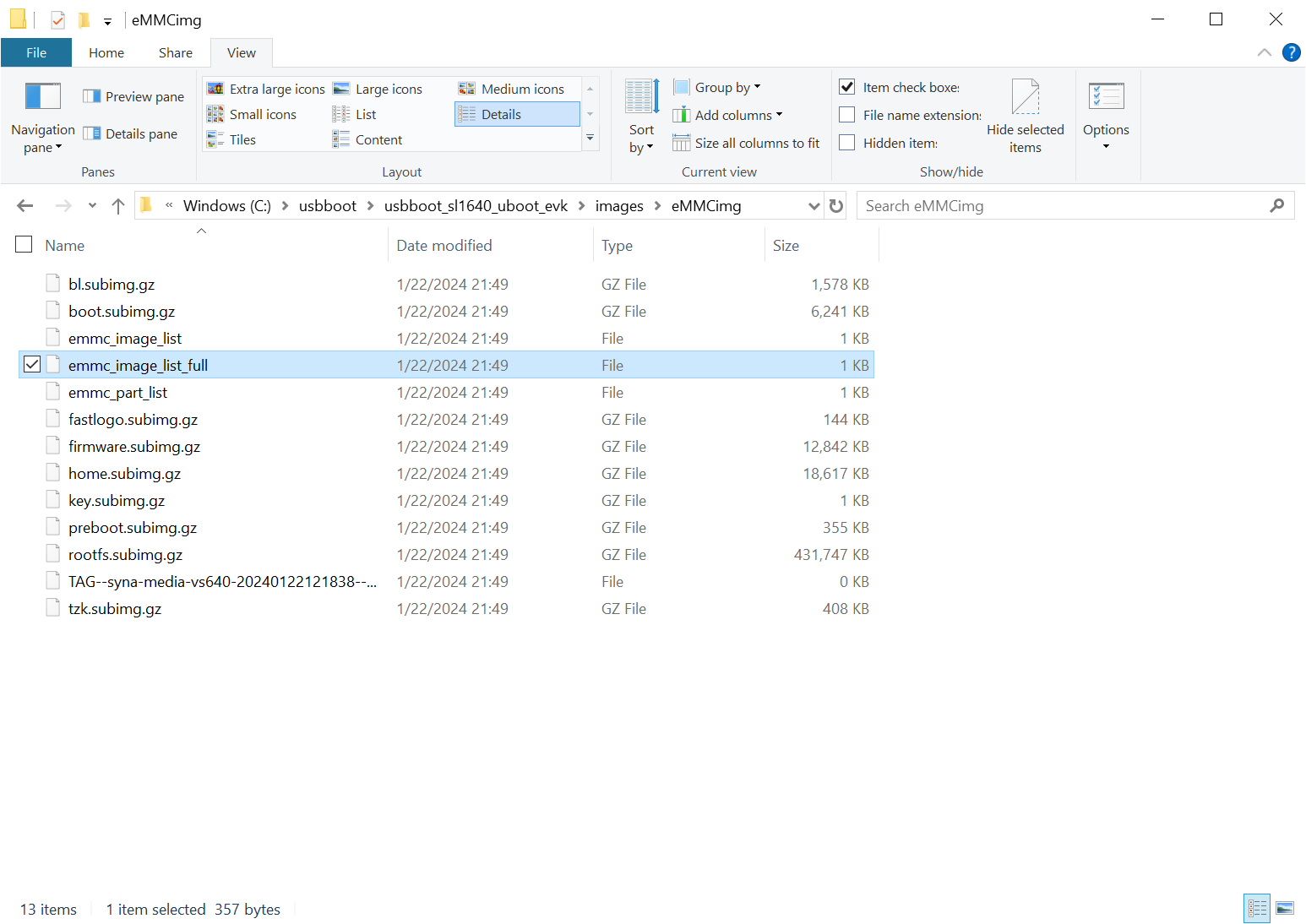
A screenshot of the Astra image
The “Astra System Image” is a directory containing several subimg files and emmc_part_list, emmc_image_list, and emmc_image_list_full. The emmc_part_list describes the GUID Partition Table (GPT) which will be used for the eMMC. The emmc_image_list* files specify which sub image files should be written to which partition on the eMMC.
Example SL1640 Partition Table:
Partition name |
Contents |
Can be removed |
Accessed by |
|---|---|---|---|
factory_setting |
MAC address and other factory provisioned files, used by user space |
No |
Linux user space |
key_a |
AVB keys, user keys (A copy) |
Yes |
Early boot (boot partition) |
tzk_a |
TrustZone Kernel (A copy) |
Yes |
Early boot (boot partition) |
key_b |
AVB keys, user keys (B copy) |
Yes |
Early boot (boot partition) |
tzk_b |
TrustZone Kernel (B copy) |
Yes |
Early boot (boot partition) |
bl_a |
OEM Boot loader (A copy) |
Yes |
Early boot (boot partition) |
bl_b |
OEM Boot loader (B copy) |
Yes |
Early boot (boot partition) |
boot_a |
Linux Kernel, loaded by OEM bootloader (A copy) |
No |
OEM boot loader (bl_a) |
boot_b |
Linux Kernel, loaded by OEM bootloader (B copy) |
No |
OEM boot loader (bl_b) |
firmware_a |
GPU / DSP / SM firmwares, loaded by early boot, required (A copy) |
Yes |
Early boot (boot partition) |
firmware_b |
GPU / DSP / SM firmwares, loaded by early boot, required (B copy) |
Yes |
Early boot (boot partition) |
rootfs_a |
Root file system, used by Linux, can be changed (A copy) |
No |
Linux (boot_a) |
rootfs_b |
Root file system, used by Linux, can be changed (B copy) |
No |
Linux (boot_b) |
fastlogo_a |
Fast logo image, loaded by OEM bootloader, can be changed (A copy) |
No |
OEM bootloader (bl_a) |
fastlogo_b |
Fast logo image, loaded by OEM bootloader, can be changed (B copy) |
No |
OEM bootloader (bl_b) |
devinfo |
Device information (such as serial number, mac address ) required |
Yes |
Early boot (boot partition) |
misc |
Boot control settings, required |
Yes |
Early boot (boot partition) |
home |
Mounted in /home, can be customized |
No |
Linux user space |
Updating the Firmware using USB
Astra Machina supports updating firmware using USB.
Setting up the USB Boot Environment
Booting from USB requires the usb_boot software tool to be the installed on a host system. Windows, Mac, and Linux hosts are supported. Windows systems also require the Synaptics WinUSB Driver. Mac and Linux systems do not require any additional drivers. USB Boot also requires setting up the serial console as described in the Setting up the Serial Console section above. This section covers how to configure the host system and prepare for USB booting.
Hardware Setup
To run usb_boot you will need to connect the USB-TTL board and cable to Astra Machina as described in the Setting up the Serial Console section above. This will allow you to see console messages during the flashing process and input commands to the bootloader. You will also need to connect a USB cable from the host system to the USB Type-C USB 2.0 port on Astra Machina (next to the ethernet port).
Astra Machina Component Diagram with USB Type-C USB 2.0 port highlighted
Installing the WinUSB Driver (Windows Only)
Windows requires a special USB kernel driver to communicate with Astra Machina over USB. Please download the driver from GitHub. Linux and Mac hosts can access the Astra board from user space and do not need any additional kernel drivers.
After downloading and decompressing the USB Boot software package, right
click on the SYNA_WinUSB.inf file in the Synaptics_WinUSB_Driver
directory. Select “Install” from the drop down menu.
Note
Installing the Windows driver requires an account with administative privileges. Please contact your System Administrator if you do not have sufficient privileges.

Install the driver
After installing the driver, the Astra Machina will show up in the Windows Device Manager as the “Synaptics IoT: Tools package USB Driver for Synaptics Processors” when operating in USB Boot mode.
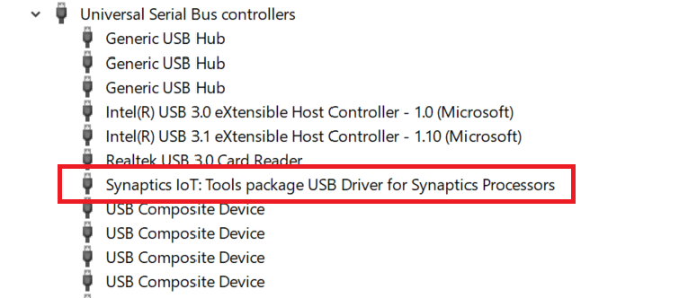
Devices listed by the operating system after installing the driver
Running the USB Boot Tool
First download the usb_boot tool from GitHub
if you have not done so previously.
Note
Please check the release notes to confirm that you have a compatible version of usb_boot.
Release Notes v1.0.0
The usb_boot tool communicates with Astra Machina over USB.
Each Astra Machina variant will have its own usb_boot directory. Included in each
directory will be a usb_boot binary and the run script used to run it.
The directory will also contain an images directory which contains all of the
image files needed to boot the board over USB. This include images which contain
the USB U-Boot bootloader.
On Windows, double click on the run.bat file to launch the tool. This script will execute the binary using the specific options required for Astra Machina variant being used.
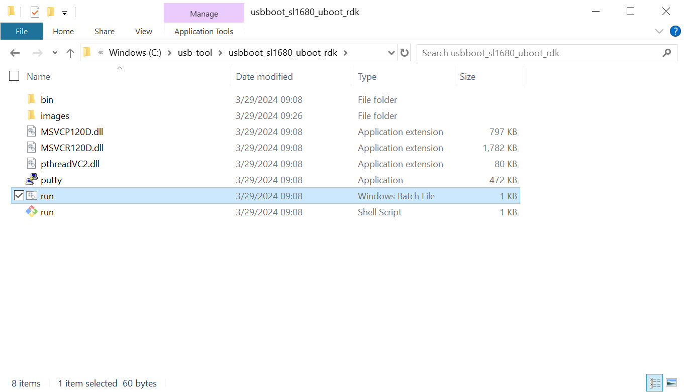
Directory containing the USBBoot tool on Windows
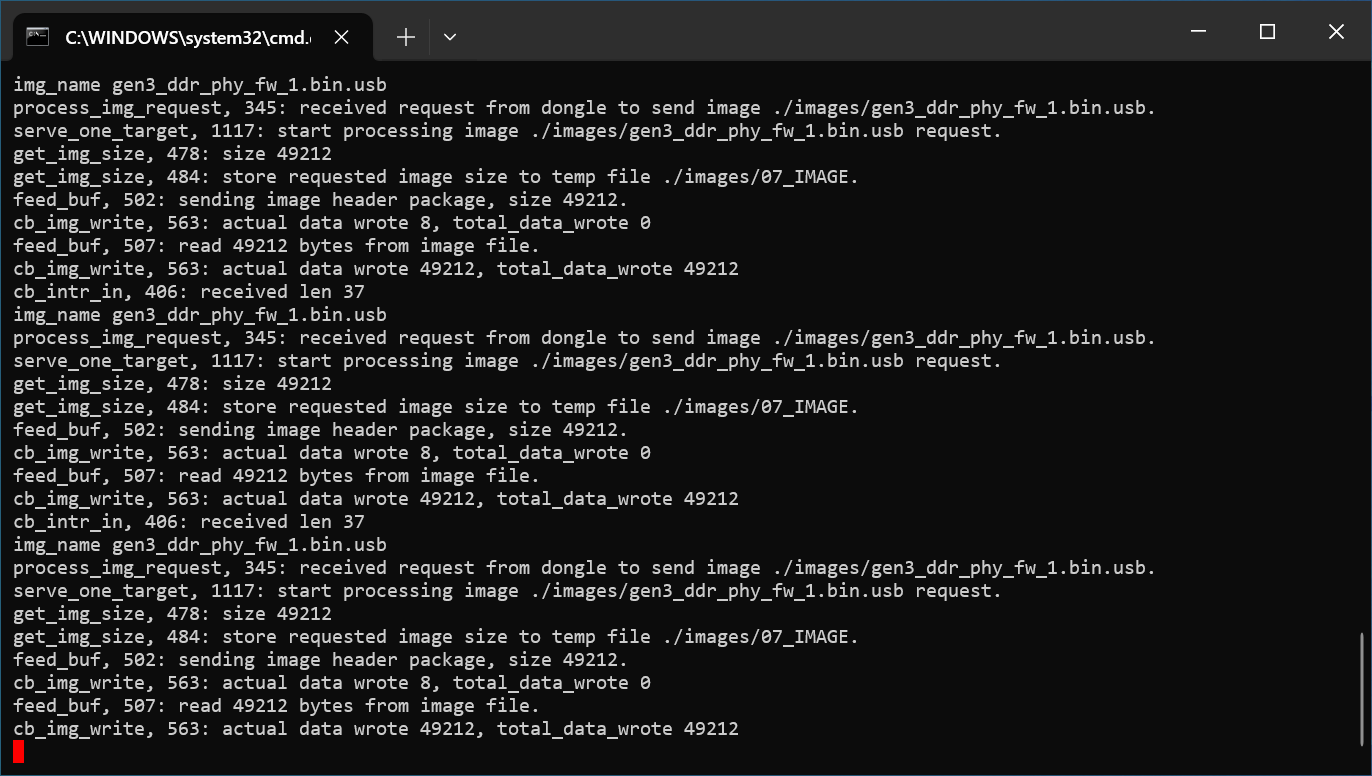
After running the run.bat a window will open showing the status of the flash process.
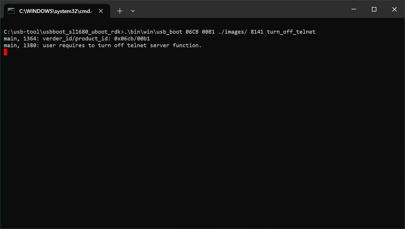
Output of the usb_boot tool on Windows
On Mac, right click on the directory which contains the version of usb_boot which matches
the Astra Machina variant which you are about to boot. From the drop down select Services -> New Terminal at Folder.
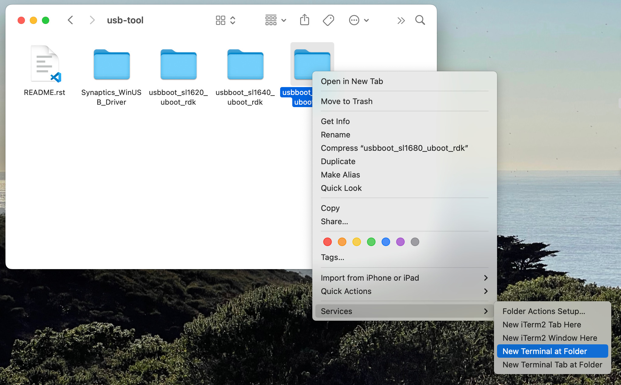
Opening a Terminal for USB Boot on Mac
This will open a terminal inside of the selected usb_boot directory. From there run the run.sh script to
run the tool. You may be prompted for your password since the script internally calls sudo. The tool
requires additional permissions to interface with USB devices and access system resources.
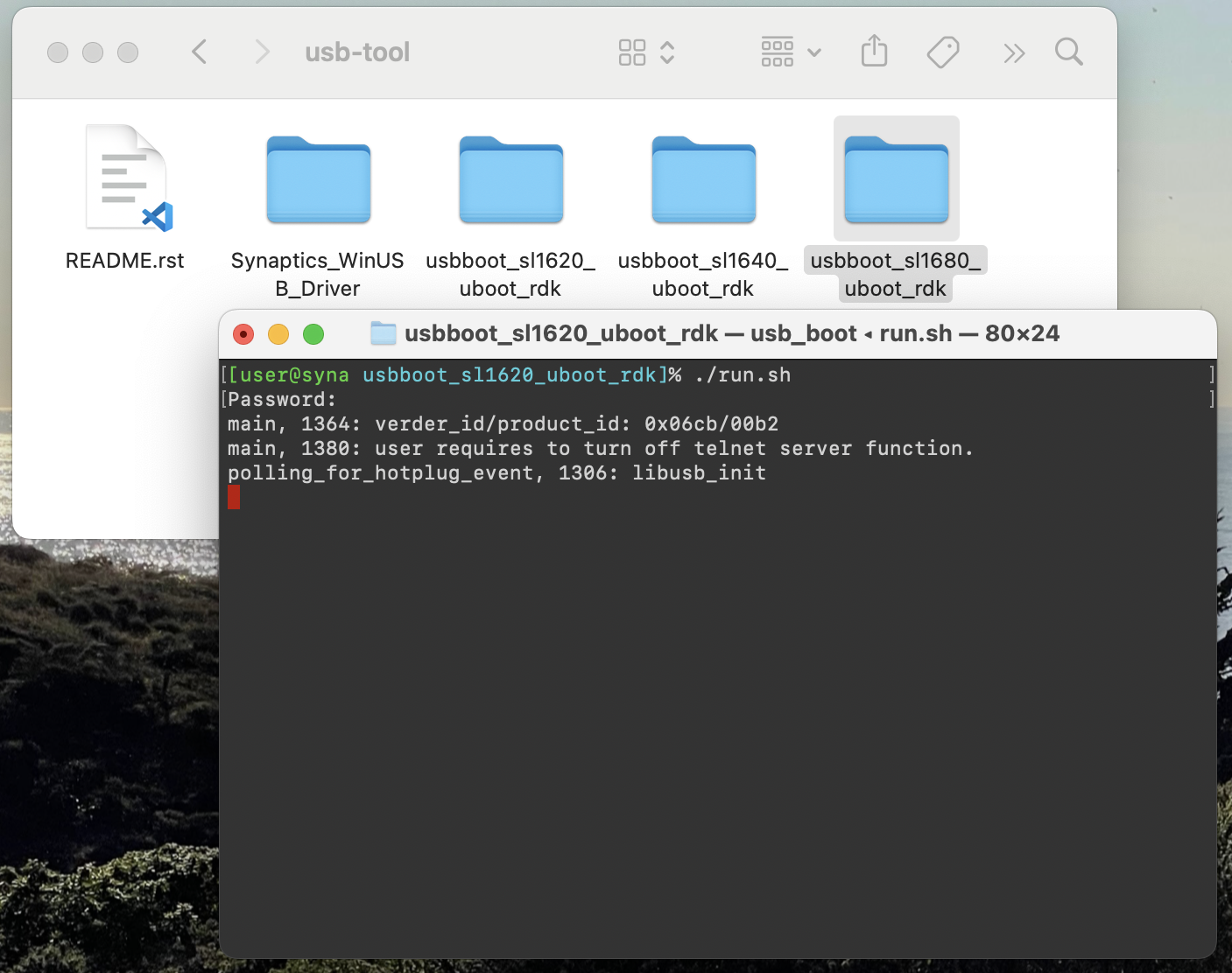
Output of the usb_boot tool on Mac
On Linux, right click on the directory which contains the version of usb_boot which matches
the Astra Machina variant which you are about to boot. From the drop down select Open in Terminal.
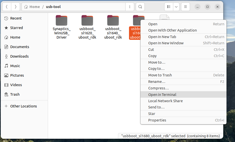
Opening a Terminal for USB Boot on Linux
This will open a terminal inside of the selected usb_boot directory. From there run the run.sh script to
run the tool. You may be prompted for your password since the script internally calls sudo. The tool
requires additional permissions to interface with USB devices and access system resources.
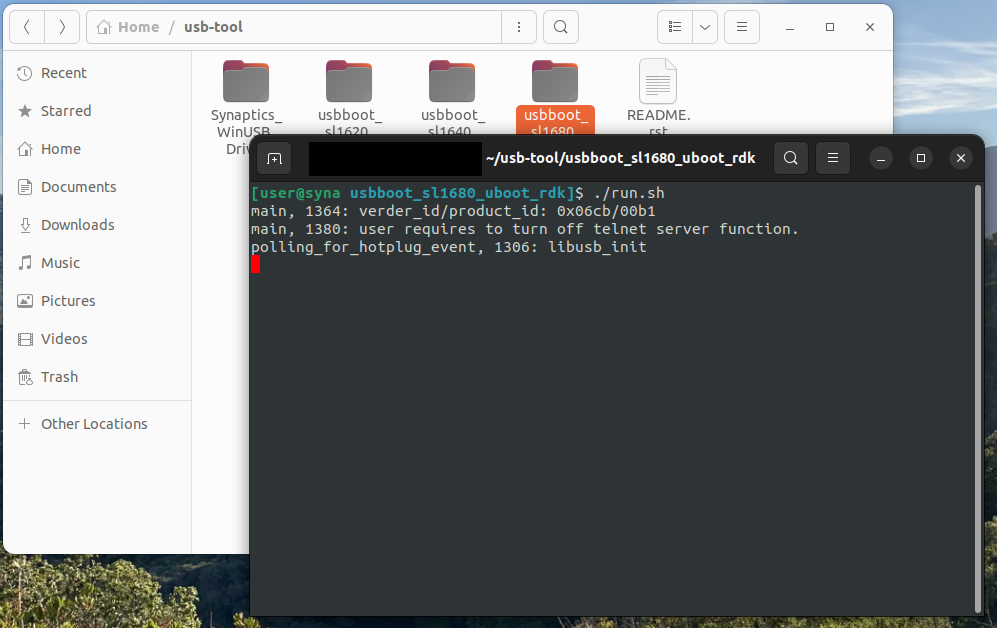
Output of the usb_boot tool on Linux
Booting using USB Boot
Once the usb_boot environment has been setup and the usb_boot tool is running on the host system, Astra Machina will need to be placed into USB Boot mode. To do that press and hold the “USB_BOOT” button on the I/O board. Then press and release the “RESET” button. Be sure to hold the “USB_BOOT” button long enough so that the board can reset and detect that the “USB_BOOT” button is pressed. After booting into USB Boot mode the U-Boot prompt “=>” will be displayed in the serial console.
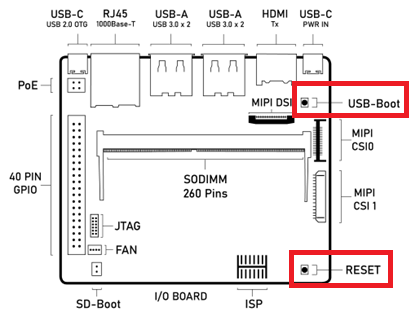
Astra Machina Component Diagram with USB_BOOT and RESET buttons highlighted
Output of the usb_boot tool and the serial console after successful boot
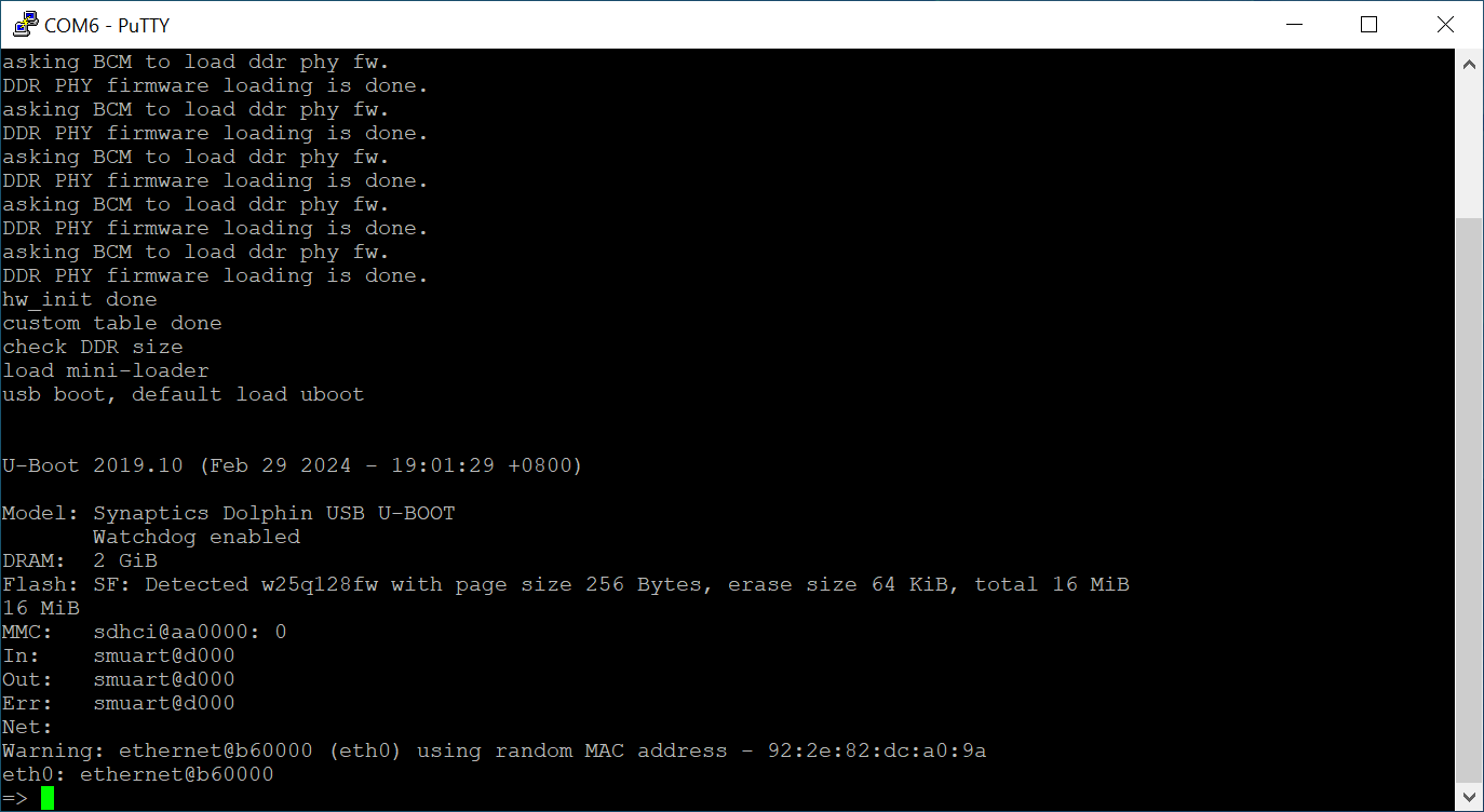
Serial Console after booting using USB Boot
Note
Astra Machina will not show up in the Window’s Device Manager or be seen by the tool until putting the device into USB Boot Mode. Hold down the USB_BOOT and press the RESET button as described above.
Flashing Firmware to eMMC using USB Boot
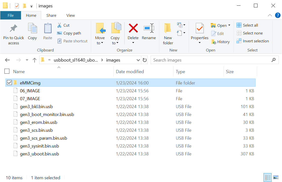
Directory with files used to flash the eMMC image
When booting from USB, the usb_boot tool allows transferring the eMMC image directly over the USB interface. To flash the eMMC image via USB, copy the image files to the ‘images’ folder in your Astra Machina variant’s usb_boot tool directory.
Write the image to the eMMC using the command:
=> l2emmc eMMCimg
The parameter eMMCimg is the name of the image directory under the usb_boot tool’s images directory.
Resetting
Astra Machina will boot into linux if a valid image has been written to the eMMC when the board is powered on. After writing an image to the eMMC, issue the reset command in U-Boot. Press the “RESET” button on the board, or power cycle the board to boot into Linux.
U-Boot reset command:
=> reset
Note
Make sure that the SD-Boot jumper is not attached when booting from eMMC. Otherwise,
the device will boot from internal SPI flash or an SD Card. See Booting from SPI and SD Cards.
Updating the Firmware from SPI
As described in Booting from SPI and SD Cards, Astra Machina has an internal SPI flash chip which contains the SPI U-Boot bootloader. This allows doing firmware updates without using a USB host system. Images can be loaded using an external USB drive or downloaded from a TFTP server on a local network.
Note
Please check the release notes to confirm that you have a compatible version of SPI U-Boot installed on the internal SPI flash. Release Notes v1.0.0
Setting up the SPI Boot Environment
Booting from the internal SPI flash does not require any additional software on the host besides the software for using the serial console as described in the Setting up the Serial Console section above.
Hardware Setup
For SPI boot, you will need to connect the USB cable for the serial port as described in the Setting up the Serial Console section above. This will allow you to see console messages during the flashing process and input commands to the SPI U-Boot bootloader. You will also need a USB drive or Ethernet cable depending on where the eMMC image files are located. The USB drive can be inserted into any of the 4 USB Type-A USB 3.0 ports or the USB Type-C USB 2.0 port (may require USB Type-C to USB Type-A adaptor).
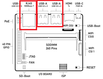
Astra Machina Component Diagram with USB and Ethernet ports highlighted
Flashing Images from a USB Drive
To flash an Astra system image from an external USB drive simply copy the image directory to the USB drive. The USB drive will need a partition with a Fat32 formatted file system and enough capacity to fit the Astra system image.
Write the image to eMMC using the command:
=> usb2emmc eMMCimg
The parameter eMMCimg is the name of the image directory on the USB drive.
Flashing Images from a TFTP Server
To flash an Astra system image from a TFTP server you will first need to connect Astra Machina to a local network using the ethernet port. Copy the Astra image to the TFTP server so that it can be accessed by the device over the network. Once the device is connected to the network, boot to the U-Boot prompt.
Initialize networking and request an IP address from a DHCP server on the local network:
=> net_init; dhcp;
=> setenv serverip 10.10.10.10;
Write the image to eMMC from the TFTP server using the command:
=> tftp2emmc eMMCimg
The parameter eMMCimg is the name of the image directory on the TFTP server.
Note
SPI U-Boot initializes the network and requests an IP automatically.
The net_init and dhcp commands not needed when using SPI U-Boot.
Note
In the examples above the TFTP server’s address is 10.10.10.10. Please replace this IP with the IP address of the server hosting TFTP.
Updating Internal SPI Flash Firmware
The internal SPI flash on Astra Machina can also be updated using the methods described above. You can find the latest versions of the SPI images on GitHub.
Flashing Image from USB Boot
To update the internal SPI flash firmware using usb_boot you must first follow the steps in section Setting up the USB Boot Environment.
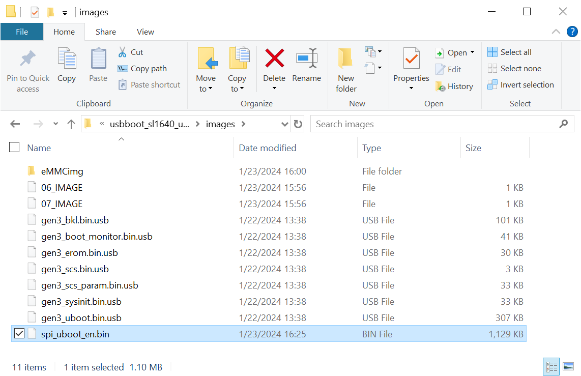
Directory with files used to flash the SPI flash
Once Astra Machina has booted U-Boot from USB, program the SPI flash by copying the SPI image file to the “images” directory in the usb_boot tool’s directory.
Then write the image to the SPI flash using the commands:
=> usbload u-boot-astra-v1.0.0.sl1680.rdk.spi.bin 0x10000000
=> spinit;
=> erase f0000000 f01fffff; cp.b 0x10000000 0xf0000000 0x200000;
An optional backup copy of the SPI flash firmware can be installed using the command:
=> erase f0200000 f03fffff; cp.b 0x10000000 0xf0200000 0x200000;
Flashing Image from an External USB Drive
To update the internal SPI flash firmware using an external USB drive, simply copy the image to the drive. The USB drive will need a partition with a Fat32 formatted file system.
Write the image to SPI flash using the following commands:
=> usb start; fatload usb 0 0x10000000 u-boot-astra-v1.0.0.sl1680.rdk.spi.bin;
=> spinit;
=> erase f0000000 f01fffff; cp.b 0x10000000 0xf0000000 0x200000;
An optional backup copy of the SPI flash firmware can be installed using the command:
=> erase f0200000 f03fffff; cp.b 0x10000000 0xf0200000 0x200000;
Flashing Image from TFTP Server
To update the internal SPI flash firmware by downloading it from a TFTP server, simply copy the image to the TFTP server.
Write the SPI image to the SPI flash from the TFTP server using the command:
=> net_init; dhcp;
=> setenv serverip 10.10.10.10;
=> tftpboot 0x10000000 u-boot-astra-v1.0.0.sl1680.rdk.spi.bin;
=> spinit;
=> erase f0000000 f01fffff; cp.b 0x10000000 0xf0000000 0x200000;
An optional backup copy of the SPI flash firmware can be installed using the command:
=> erase f0200000 f03fffff; cp.b 0x10000000 0xf0200000 0x200000;
Note
SPI U-Boot initializes the network and requests an IP automatically.
The net_init and dhcp commands not needed when using SPI U-Boot.
Note
In the examples above the TFTP server’s address is 10.10.10.10. Please replace this IP with the IP address of the server hosting TFTP.